|
August 1959 Popular Electronics
 Table
of Contents Table
of Contents
Wax nostalgic about and learn from the history of early electronics. See articles
from
Popular Electronics,
published October 1954 - April 1985. All copyrights are hereby acknowledged.
|
Ground is ground the world
around. That's a saying that I have often heard Ham radio operators say aloud and
in writing. In a general sense, it's true, but on a local level grounds can vary
widely from location to location, even within a few hundred feet. It is true both
for direct current and low frequencies and for frequencies in to the GHz regions.
It has to do with the conductivity of the soil and/or rock in the area as well as
the amount of moisture and other elements in the ground. Antenna guys like to run
conductive (usually copper) "radials" out from the mounting pole or tower in order
to create a sufficient local reference ground, and electric power distribution engineers
often need to salt the ground around substations with ionic compounds in order to
create sufficient conductivity to provide a safe grounding system. This article
from the August 1959 edition of Popular Electronics is a good primer on
the subject.
After Class: Ground, Grounds, and Grounded
 By Saunder Harris By Saunder Harris
WINXL
Why is a good ground so important? Why are some circuits grounded and others
not grounded? What is the physical and electrical meaning of the ground symbol when
it appears in a diagram?
Grounding actually means making an electrical connection between a piece of equipment
or circuit and the earth, thus bringing the connected point to the earth's neutral
potential. There are many ways of accomplishing this. The most common way is by
connecting the equipment to a cold water pipe by means of a wire and a metal grounding
clamp.
Why specifically a cold water pipe? Well, a cold water pipe goes directly to
the outside water line which is buried in the earth. A hot water pipe is connected
to a furnace or hot water heater and is not a direct ground connection.
Another way of making a ground connection is by connecting the equipment to a
metal rod which has been driven deep into the earth. The metal rod is called a ground
rod and, to be effective, should go at least eight feet into the ground. A properly
installed ground rod is shown in Fig. 1.

Fig. 1 - Ground rod system of grounding is good if the rod
is driven well into some moist earth.
If you check your TV antenna, you may find that a ground rod is part of the installation,
as is a lightning arrestor. Should lightning strike the antenna, it would find an
easier path through the lightning arrestor to the ground rod, and thus into the
earth, than through your house.
A Good Ground
Whether or not a ground is "good" is determined by the amount of ohmic resistance
between the ground rod, or other means of grounding used, and the earth. The less
this "earth resistance," the better the ground. The actual resistance measurement
is made with an instrument called a megohmmeter which applies a high voltage to
a resistance and then measures the current flow.
There are many factors that determine the earth resistance. Some of the more
important are:
1. Moisture content of the soil surrounding the grounding element.
2. Composition of the soil. For example: clay is a good contact, rock a poor
one.
3. Temperature of the soil.
4. Size, shape, and number of the grounding elements buried in the earth. The
more element area in contact with the soil, the better the ground.
Circuit Grounds
The ground in an electrical circuit is the circuit's electrical reference point.
Normally when something is "above" ground, it is positive, since the negative side
of the circuit is usually grounded. There are times, however, when the positive
side is grounded, as in some of the new 12-volt automobile electrical systems. In
such cases, the potentials would be considered negative or below ground. Before
installing mobile equipment in a car, it is important to determine whether the positive
or the negative terminals of the battery are grounded.
When a circuit is grounded and the circuit diagram shows various parts to be
at ground potential by the ground symbol, it means, in effect, that these parts
are electrically connected. This is generally done by using the chassis as a common
grounding point and then connecting the chassis to an external ground.
Equipment is grounded as a safety measure as well as for proper operation of
the circuit. If a ground connection is made to the chassis, possibility of shock
through contact with the chassis is eliminated since both you and the chassis are
at "ground potential."
There are some circuits, in which the chassis is "hot," that should never be
grounded. A common example of equipment which should not be grounded is the typical
a.c.-d.c. table radio. The instructions which come with these sets generally state,
"Caution: Do not connect a ground wire to this set." Since you may have either ground
potential or 117 volts a.c. on the chassis (depending on which way you insert the
a.c. plug into the power line), these inoffensive-appearing little sets should be
handled with due respect, and never be operated outside of their insulated cabinets
without taking proper precautions.
Grounds and Antennas
An antenna is nothing more than a conductor whose specific job is to radiate
or receive electromagnetic energy. Very often in ham radio the same antenna serves
for both transmitting and receiving through the use of a switching arrangement.
In this discussion we shall limit ourselves to the role that the earth, or ground,
plays in the functioning of the antenna system.
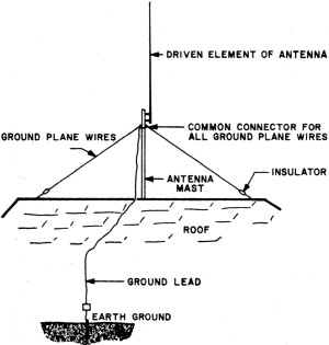
Fig. 2 - Ground plane system is useful when an antenna must
be installed at a distance from an external ground.
Although antennas are sometimes discussed without taking the earth into consideration,
we cannot ignore the earth. When the antenna radiates electromagnetic energy, the
earth acts as a reflector for energy which is directed in a downward direction.
These waves are reflected back by the earth and combine with the waves which have
been radiated directly from the antenna.
If the reflected wave and the direct wave are in phase, that is, if their maximums
and minimums coincide, they tend to strengthen each other. If they are out of phase,
or do not coincide, the reflected wave weakens the direct wave to the point where,
if the two waves are 180° out of phase, cancellation occurs. The way the two waves
combine depends to a large extent on the relationship of the antenna to the ground
beneath it. Is the ground a good conductor or a poor conductor? Is it rocky? Is
it wet or dry? Is the antenna high above the earth? All of these factors are important.
Currents are induced in the earth by that portion of the radiated wave which
travels along the ground and is known as the ground wave. Valuable energy is dissipated
into the earth by the ground wave and every attempt is made to keep ground-wave
losses to a minimum. Fewest losses occur when the wave travels over ground which
is a good conductor. This is the reason many commercial stations place their antenna
systems near water or marsh lands, the water or wet earth being a much better conductor
than dry earth.
Where this physical placement is not possible, in order to make the ground around
the antenna as conductive as possible, metal rods or mesh screens are buried near
the surface of the earth. They extend about one-half wavelength to either side or
radially around the antenna. The actual height of the antenna then becomes its height
above this ground screen.
Many times it is practical to mount a vertical antenna on the roof of a building
at an inconvenient distance from a good grounding point. A ground system is still
for the antenna to operate properly and may be accomplished by simulating a ground
condition at the base of the antenna through the use of a ground plane system (see
Fig. 2).
In the ground plane system, copper wires cut to quarter wavelengths of the frequencies
to which the antenna is tuned are attached radially, with wires of the same length
opposite each other, to the base of the antenna mounting. They are insulated from
the antenna's driven element and the roof but connected to a good earth ground and
the transmission line shield.
In effect, the ground plane system provides a ground cut to specified wavelengths
and then suspended in mid-air at the point where it is needed. In practice, ground
plane radials generally act as supports for the vertical antenna mast as well as
being part of the electrical installation.
Safety and Efficiency
A sound knowledge of basic ground theory and procedures is necessary for each
person who works or experiments with electronic devices. Good grounding techniques
assure the operation of electronic equipment at maximum efficiency and with minimum
electrical shock hazard.
Posted March 23, 2020
(updated from original post on 1/23/2012)
"After Class" Topics
|