|
December 1957 Popular Electronics
 Table
of Contents Table
of Contents
Wax nostalgic about and learn from the history of early electronics. See articles
from
Popular Electronics,
published October 1954 - April 1985. All copyrights are hereby acknowledged.
|
This installment of the After
Class series in the December 1957 edition of Popular Electronics deals
with inductors. It is a beginner-level introduction to how reactive components behave
in circuits. For some reason the concept of magnetism's influence on electrical
current (present with inductors but not capacitors) seems to be more difficult to
comprehend than that of electrons, even though
James Clerk Maxwell shows in the mid 1800s that the two phenomena
are interrelated. I am tempted to say that back in the 1950s when this article appeared,
people were less familiar with the relatively new concept of electronics, but in
thinking about it, your typical 2019 reader is probably even less likely to know
anything at all about electronics or the way basic components work. I would bet
that maybe 1% could even tell you the difference between AC and DC current - or
the difference between current and voltage for that matter.
After Class: Special Information on Radio, TV, Radar and Nucleonics
- Using Inductors
 "I know what an inductor
is - I think - but I'm pretty hazy as to its use in an electronic circuit. And while
we're talking about inductors, exactly what's the difference between a solenoid
and a toroid, which I understand are two forms of inductors'!" "I know what an inductor
is - I think - but I'm pretty hazy as to its use in an electronic circuit. And while
we're talking about inductors, exactly what's the difference between a solenoid
and a toroid, which I understand are two forms of inductors'!"
Picture a complicated highway interchange with no directional signposts, traffic
lights, or highway police, and you have a pretty good idea of what an electrical
circuit would be like without "oppositional" components that guide, cajole, and
coax electrons to follow prescribed paths. Resistors, capacitors, and inductors
- occurring singly or in various combinations - comprise the fundamental oppositional
elements that direct electronic traffic so skillfully even in complex circuits.
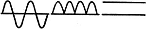
Fig. 1 - Rectifier changes a.c. to pulsating d.c.
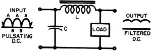
Fig. 2 - Filter smooths pulsating direct current.
Ordinary resistors are undiscriminating components; they oppose d.c., a.c., high
frequency, and low frequency alike. A given current of any type passing through
a specific resistor causes the same voltage drop. Capacitors are different; they
oppose changes of voltage in any circuit of which they form a part but do not react
significantly to rapid current variations.
Inductors vs. Capacitors. An inductor may be viewed as the exact
opposite of a capacitor. Made up of turns of wire in the form of a coil, an inductor
opposes current rather than voltage changes, especially when these variations occur
at a high frequency. This characteristic makes the inductor a useful complement
to the capacitor in a power supply filter circuit.
A full-wave rectifier circuit changes alternating current to pulsating direct
current (Fig. 1). This "hill and valley" formation of pulsating d.c. is usually
not suited for operating d.c. electronic equipment until the "valleys" are filled
in .
Consider the filter circuit shown in Fig . 2. As the pulsation appears across
the capacitor C, the latter charges to the peak voltage (points labeled A) of the
input wave. When a valley appears (points labeled B), the capacitor attempts to
discharge through the inductor L into the load, which may be any device that uses
direct current.
Since such a discharge would constitute a sudden surge of current, the opposition
that inductor L offers to such an abrupt change forces C to retain most of its charge
until the next peak appears to bring it back to full charge again. In this way,
L assists C in maintaining the circuit voltage constant, an action necessary to
change pulsating current into pure d.c. In this circuit, L is termed a choke.
Opposition Factors. The opposition an inductor or choke presents
to varying currents depends upon two factors: (1) how fast the current varies (frequency),
and (2) the physical construction of the coil - the number of turns, turn spacing,
coil diameter, and kind of core. A filter choke of the type just described has hundreds
of turns of fine wire, an iron core, and is said to have a high inductance. Just
as resistance is measured in ohms, e.m.f. in volts, and current in amperes, inductance
is measured in henrys. The symbol "L" signifies inductance. Smoothing chokes usually
run from 10 to 30 henrys.
Any time a circuit condition calls for choking off a rapidly varying current,
an inductor of the correct size used in conjunction with a properly chosen capacitor
can do the job. For example, suppose an electron tube is generating a current of
high frequency, say 1,000,000 cycles per second (1 mc.). This tube is fed d.c. voltage
and current from a power supply, but the high-frequency current is not to be permitted
to flow backward through the supply.
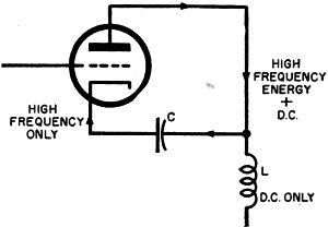
Fig. 3 - "L" blocks high frequency, "C" passes it.

Fig. 4 - The toroid has a doughnut-shaped core.
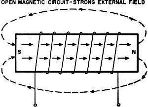
Fig. 5 - Solenoid is wound around straight core.
Connecting an inductance and capacitor as shown in the partial schematic (Fig.
3) fulfills this requirement by permitting the d.c. to flow through the inductor
but opposing the high-frequency current back-flow through the inductor. The capacitor
provides an easy path for the high-frequency current to return to the tube - a necessary
arrangement to assure a complete circuit for this energy. An inductor like this
has relatively few turns wound on a ceramic or plastic core; its inductance might
range from 2 to 10 millihenrys (0.002 to 0.01 henry). Because the frequency is so
high, not much inductance is needed to place a barrier in front of the incoming
varying current.
In summary, an iron core coil of many turns has a high inductance and is especially
useful as a choke in low-frequency circuits; high-frequency hookups call for low-inductance
coils of few turns on non-magnetic cores.
Toroids and Solenoids. Over the years, toroids have been used desultorily by
many of the larger overseas communications companies for the special filter applications
in which they perform particularly well. The last decade has seen a steady growth
in the number of circuits and devices in which toroid ally wound coils have come
to be preferred over solenoid types.
The word toroid describes a method of coil winding.
Fig. 4. Turns are placed around a doughnut-shaped core which forms an absolutely
closed magnetic circuit as illustrated. A solenoid, on the other hand, is generally
defined as a coil fabricated on a straight core, sometimes iron, and other times
air or non-magnetic solids like plastics or fiber - see Fig. 5. Certain types of
transformers have two separate solenoid coils on a common core.
What is the secret of the toroid's sudden rise to prominence? Known for many
years to be vastly superior to solenoids in certain important respects, toroids
were avoided by designers and manufacturers for two reasons. Suitable core materials
were not available, especially in applications involving the higher audio frequencies
and the radio frequencies. And automatic machines for winding turns around a doughnut
core were virtually unobtainable at any price.
OPEN MAGNETIC CIRCUIT-STRONG EXTERNAL FIELD
Neither of these problems exists today. High-speed automatic toroid winders form
these inductors just as quickly as solenoids; and modern core materials like Permalloy
dust, the ferrites and mu-metal make them practical for use at the higher frequencies.
The "open" magnetic circuit of the solenoid forces its lines of force to travel
through the surrounding open space to link with the core at both ends, whereas the
"closed" path of the toroid core confines the field to the molecules of the core
so that there is little or no external field. Two very significant advantages arise
from this behavior: first, it makes possible higher inductances with fewer turns
of wire, and second-probably much more important - it does away with the need for
careful shielding. Where there is no external field surrounding inductors, there
can be no electromagnetic coupling to cause un-wanted regeneration and oscillation.
In general, toroids may be stacked one on top of the other in the same case without
interaction for the reason given above. Their most important use at present is in
wave-filters (resonant and non-resonant traps and peaking circuits). They may be
made very stable and unresponsive to temperature changes and vibration, and may
be designed with very high Q's even at frequencies up to 60 kc. or 70 kc.
Look for toroid transformers to replace solenoid types in many of the forthcoming
high-fidelity systems still on the design boards.
Posted February 1, 2019
(updated from original post on 8/3/2011)
"After Class" Topics
|


