|
May 1955 Popular Electronics
 Table of Contents Table of Contents
Wax nostalgic about and learn from the history of early electronics. See articles
from
Popular Electronics,
published October 1954 - April 1985. All copyrights are hereby acknowledged.
|
"After Class" is a
long-running feature of Popular Electronics magazine that covered a
very wide range of topics. In most instances a single major theme is presented,
but in this May 1955 issue there are five separate areas: the Faraday shield,
binary notation, using a tuning fork to resonate a tank circuit, and two quizzes
(one on resistance and capacitance and another on power supplies). On the topic
of Faraday shields, I have to tell you about an e-mail I recently received from
an RF Cafe visitor. He wrote asking whether there was any atmospheric pressure
at which satellite radar could not penetrate to the Earth's surface. I could be
wrong, but usually questions like that are asked by people who believe in a
government conspiracy to surveil (and ultimately control) the populace. I used
to dismiss such notes as being from lunatics, but with all the cameras
everywhere and the ability to track movement via cell towers and Wi-Fi hot
spots, a degree of kinship is beginning to develop. Notwithstanding the former
admission, my response was that no level of pressure survivable by humans would
block radar signals - after all, even Venus' 90-atm atmosphere pressure prevents
us from radar-mapping it - a possibility would be to suspend a tin foil shield
(Faraday shield) at troposphere level. The only drawback, I wrote in the
response, was that it would leave too little tin foil for constructing personal
tin foil hats ;-)
After Class: The Faraday Shield, Binary Notation, Tuning Fork Oscillators, and
Power Supply Quiz
Whether it is simple or complex, basic or advanced, amateur or commercial - every
electronic device depends upon the correct combination of resistors and capacitors
to help it function according to plan. In this article, some of these combinations
are to be investigated with a view to learning something about their behavior in
electronic circuits.
Resistors and capacitors are controlling elements which guide and modify electron
streams so that the circuit performs as its designer intended it to perform. Although
they have vastly different influences in electrical circuits, it is just this difference
that makes them so useful when used in combinations that have special jobs to do.
Generally, a resistor does not discriminate between different kinds of current;
that is, if a resistor is rated at 1,000 ohms, it offers this resistance to any
kind of current, either a.c. or d.c., and, in the case of alternating current, it
makes no difference what the frequency of the alternations may be - the resistor
still opposes the flow of current to the same extent as it opposes d.c.
A capacitor is a different "breed". It exhibits "selectivity" in its opposition
to electricity. A capacitor may be chosen to provide an easy path for alternating
current, while at the same time, d.c. is completely blocked. Another way to express
this idea is to call a capacitor an open circuit for d.c., but a conductor for a.c.
provided that it has sufficient capacitance and that the frequency of the a.c. is
high enough.
As one might gather from this statement, the amount of opposition that a capacitor
offers to the flow of a.c. depends upon two things: the size of the capacitor and
the frequency of the current. An easy way to keep this relationship in mind is to
remember that if either the capacitance of the capacitor or the frequency of the
a.c. is raised, the opposition is decreased. Since the term "resistance" is reserved
for resistors, the influence of a capacitor on the amount of a.c. that flows through
the circuit is called the "reactance", but it is measured in ohms just like resistance.
Expressed mathematically, capacitive reactance, XC, in ohms, equals
1/(2πƒC), where ƒ is the frequency in cycles-per second and C is the
capacitance in farads or ƒ is in megacycles and C is in micro-farads. This
dues not hold true at extremely high frequencies, but it does apply in all ordinary
electronic equipment. The exact mathematical computation is not required for a general
understanding of the working of simple circuits.
To illustrate the effect of both resistance and capacitive reactance in a practical
circuit, consider the diagram. Suppose that a certain electrical generator produces
both a.c. and d.c. mixed with each other - a very common situation in electronics.
Suppose further that there are two devices which we shall call "loads ", one of
which needs pure d.c. to operate properly, while the other requires pure a.c. A
resistor and a capacitor properly chosen as to values can separate the a.c. from
the d.c. and guide the two different currents along the desired paths. As the mixed
currents arrive at point (1) in the circuit, the d.c. "sees" the capacitor as an
open circuit through which it cannot flow, so it selects the resistor as its only
other alternative path through the circuit; thus, the d.c. passes through the d.c.
load. The a.c., upon "looking ahead ", finds an easy path through the capacitor,
while the one through the resistor appears to offer much more opposition. Therefore,
most of the a.c. chooses the path through the capacitor and the a.c. load. The function
of a resistor-capacitor (RC) combination in splitting up a.c. and d.c. and guiding
the two different currents through different parts of the circuit is called filtering.
Almost every schematic diagram in electronics contains one or more filter circuits
in which a resistor and a capacitor are used to discriminate between a.c. and d.c.
The following quiz is intended as a self check. You should be able to answer
all of the questions correctly if you have mastered the foregoing text.
Resistor & Capacitor Quiz
1. Which of the two components, a resistor or a capacitor, exhibits changing
opposition to the flow of current as the frequency changes?
2. Given a capacitor of 0.01 μfd., which of the following should be used to
replace it if the designer wishes to reduce the reactance of the circuit - a 0.1 μfd.
or a 0.001 μfd. capacitor?
3. Does the resistance of a resistor rise, fall, or remain the same as the frequency
of the current flowing through it rises?
4. Does the phrase "blocking action" describe the functioning of a resistor or
a capacitor?
5. What general name is applied to RC combinations used to separate a.c. from
d.c.?
The Faraday Shield
 Many years after James Clerk Maxwell, the
famous 19th Century physicist, proved that magnetic fields are always accompanied
by electric fields, engineers in electronics began to struggle with undesirable
effects that these force fields create. The struggle is still going on. Many years after James Clerk Maxwell, the
famous 19th Century physicist, proved that magnetic fields are always accompanied
by electric fields, engineers in electronics began to struggle with undesirable
effects that these force fields create. The struggle is still going on.
The "inseparables," as scientists sometimes term the magnetic and electric fields
emanating from coils and wires carrying radio-frequency currents, must be cautiously
handled to prevent one circuit from affecting another; otherwise, regenerative coupling,
oscillation, and locking-in phenomena may destroy circuit performance. In planning
the layout of radio receivers and similar gear, account is taken of these fields
by enclosing coils in metal shield boxes or otherwise isolating them by means of
aluminum, copper, or steel plates. The shielding metal is placed so that the fields
are confined to the immediate vicinity of the coil.
At first glance, one might wonder how an aluminum shield can could prevent an
electromagnetic field from penetrating it. It is common knowledge that iron and
steel, being magnetic materials, are highly permeable and serve as good "conductors"
for magnetic lines of force. Thus, when the lines impinge upon an iron shield can,
they keep to the path of least resistance and follow the contours of the can. This
keeps them from "getting out." Aluminum is non-magnetic, but it is a good electrical
conductor; this characteristic enables it to arrest a magnetic field in an entirely
different manner. Moving lines of force passing through aluminum induce eddy currents
in the can. (These are random currents which represent a serious loss of energy
which must be supplied by the field.) As the field loses its energy in the generation
of eddy currents, it has little or no strength left to penetrate the metal and so
remains within the confines of the shield.
An electric field terminates as soon as its lines of force encounter a good conducting
surface. Hence, an aluminum or copper shield can prevents the "escape" of both kinds
of fields, magnetic fields by eddy current losses and electric fields by conductive
termination.
Suppose one wishes to make a shield which confines the electric field of a coil
but permits the magnetic field unhampered passage. This problem is a serious one
in metal locators where the capacitance of the ground to the search coil must be
eliminated while the magnetic flux of the coil must be allowed to penetrate the
ground. Solid plate shielding, or even screen mesh, between the coil and the ground
is out of the question because of eddy current losses. The aim is to provide metal
for the electric field termination without having eddy currents in the metal.
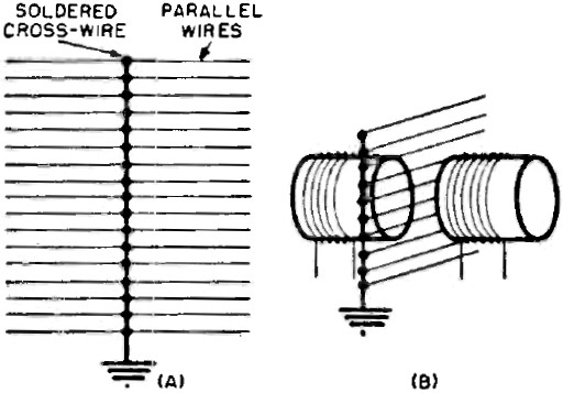
This objective is nicely achieved by using a Faraday shield. As illustrated,
this kind of shield is fabricated by gluing parallel wires to a cardboard sheet,
spacing the wires apart by a distance equal to about two wire diameters. After the
glue has set, a bare copper wire or strip is soldered across the rows at right angles;
the assembly is then run to the common ground of the equipment.
A Faraday shield provides metal conductors to terminate electric lines of force
while it offers no closed loops through which eddy currents can flow, so that magnetic
fields penetrate it with no trouble.
Binary Notation
A digital computer handles the manipulation of numbers by means of relays, lamps,
and tubes which can rest in only one of two possible states: "on" or "off." Each
of these states can, at best, represent a single digit so that only two different
digits can be indicated by a single relay or tube, one for the "on" condition and
the second for the "off" state. Our normal decimal system contains ten different
digits (1, 2, 3, 4, 5, 6, 7, 8, 9, and 0). Fortunately, there is a numbering system
that is just right for digital computers - the binary method of notation. By adhering
to simple rules, any number may be written with only two digits: 1 and 0.
To illustrate, a string of "2's" raised to successively increasing powers (from
right to left) is written across the page. 28 27 26
25 24 23 22 21 20
(256) (128) (64) (32) (16) (8) (4) (2) (1)
According to the rules of arithmetic, any number raised to the zero power, like
20, is equal to one, so we have written (1) under 20. Two
raised to the first power (21) is 2, two raised to the second power is
4 (22 = 4), two raised to the third power is 8 (23 = 8), and
so on. Using only the digits 1 and 0 we can write a number, say the number 28, by
placing either 1 or 0 under the appropriate members of the string. The rule here
is that the member of the string is to be counted or added in when 1 appears under
it and is to be ignored when 0 appears under it as in the example below (writing
the number 28):
This is really ... 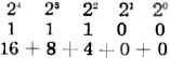
Thus, in binary notation the number 28 is written 11100.
A second example should aid in clarifying this procedure. The number 49 is written
110001. In your mind, place these digits under the members of the string starting
at the right. This gives 1 + 16 + 32 = 49. Note that the "0's" under 21,
22, and 23 were instructions to ignore these numbers and to
exclude them from the addition.
Suppose that a computer has somewhere along its progression of indicators, a
bank of 9 lights upon which has just appeared a number in binary notation as shown
in the illustration. The digit 1 is signified by a lighted lamp while 0 is indicated
by an extinguished lamp. What number is it?
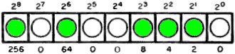
Here, the computer answer bank has given the binary number 101001110 or the sum
of 256, 64, 8, 4, and 2, to yield 334.
To increase the range or the size of the numbers, all that need be done is increase
the length of the string going left toward larger and larger powers of 2. Although
this may seem an uneconomical use of lamps and relays, it does enable great accuracy
and reliability to be obtained from equipment which is a combination of simple elements.
Tuning Fork Oscillators
 According to some of our best engineers,
particularly those engaged in work involving multiplex communication systems, the
venerable tuning fork is still the most stable generator of sine waves that has
ever been designed. Multiplexing is a system of communication in which several messages
may be sent simultaneously via a single radio-frequency channel. Unless the frequency
standards of the multiplex network are rigidly stable, erratic performance is to
be expected. One of the greatest transcontinental and transoceanic communications
companies in the world relies almost exclusively upon electrically driven tuning
forks to maintain its multiplex functioning perfectly the year round. According to some of our best engineers,
particularly those engaged in work involving multiplex communication systems, the
venerable tuning fork is still the most stable generator of sine waves that has
ever been designed. Multiplexing is a system of communication in which several messages
may be sent simultaneously via a single radio-frequency channel. Unless the frequency
standards of the multiplex network are rigidly stable, erratic performance is to
be expected. One of the greatest transcontinental and transoceanic communications
companies in the world relies almost exclusively upon electrically driven tuning
forks to maintain its multiplex functioning perfectly the year round.
An ordinary tuning fork has a natural frequency of vibration which depends upon
its physical structure (mass, length of tines, etc.). When the fork is coupled to
an oscillatory circuit like that shown in the figure, it becomes the "tank" circuit
and is kept vibrating at constant amplitude by the interchange of magnetic effects
in the electromagnetic coils.
As in the explanation of any other oscillator, we begin by assuming that power
has been applied and a steady plate current is flowing in the triode. Any chance
vibration or tremor or variation in the plate current moves the tine adjacent to
the coils toward or away from them. Assume that the movement is toward the coils.
As the mass of iron approaches the magnetic core, the flux between the poles is
altered ever so slightly, causing an induced voltage across the grid coil winding.
The polarity of the induced voltage is such that, as it is applied between grid
and ground, it charges the plate current in the triode amplifier to produce further
movement of the tine in the same direction as it started.
When the tine has reached the limit of its swing, it reverses its motion and
begins to move away from the electromagnet. As it does so, the induced voltage is
in a direction which diminishes the magnetic pull and permits the fork to move away.
Each succeeding cycle of vibration has just the tiniest bit more amplitude by
virtue of the feedback from the amplifier tube. This continues until a balance is
reached and the fork vibrates with constant amplitude at its natural frequency.
This gradual build-up of amplitude may be watched on the screen of an oscilloscope;
as one watches, the height of the waves slowly increases over a period of several
minutes until the oscillation becomes stabilized.
Power Supply Quiz
1. The ripple frequency of a full-wave rectifier operating on a 60-cycle power
line is: (a) 30 cycles-per second; (b) 60 cycles-per-second; (c) 120 cycles-per-second.
2. A resistor connected across a filter capacitor for the purpose of discharging
the capacitor after the power is turned off is known as a: (a) damper; (b) quencher;
(c) bleeder.
3. The output voltage of the rectifier circuit shown in Fig. 1 is approximately:
(a) 110 volts; (b) 155 volts; (c) 310 volts.
4. As compared with a choke input filter, a capacitor-input filter will provide:
(a) more output voltage; (b) less output voltage.
5. As compared with a choke-input filter, a capacitor-input filter will provide:
(a) better regulation; (b) poorer regulation.
6. If the iron core of a filter choke becomes saturated: (a) the inductance will
increase; (b) the inductance will decrease; (c) the inductance will remain the same.
7. The no-load output of a power supply is 200 volts. Under full-load conditions,
the output drops to 180 volts. The percentage of regulation is: (a) 20 %; (b) 10%;
(c) 5 %.
8. The cathode of a rectifier tube should be brought up to operating temperature
before the plate voltage is applied: (a) when the rectifier is a mercury vapor type;
(b) when the rectifier is a vacuum type with two diodes in one envelope; (c) when
the rectifier is a vacuum type with a metal rather than a glass envelope.
9. The inverse peak voltage rating of a rectifier tube should be at least equal
to: (a) the r.m.s. value of the a.c. input; (b) the peak value of the a.c. input;
(c) twice the peak value of the a.c. input.
10. The type of filter capacitor used most commonly in the power supplies of
radio receivers is: (a) electrolytic; (b) mica; (c) paper. Answers are given at
bottom of page. Ten correct is excellent; nine correct, very good; eight correct,
good; seven correct, fair; and six or less, poor.
p. 130
"After Class" Topics
Resistor-Capacitor Circuit Quiz
1. Capacitor.
2. 0.1 μfd.
3. Remains the same.
4. Capacitor. 5. Filter circuits.
Power Supply Quiz
1. c
2. c
3. c
4. a
5. b
6. b
7. b
8. a
9. c
10. a
|