|
January 1956 Popular Electronics
 Table
of Contents Table
of Contents
Wax nostalgic about and learn from the history of early electronics. See articles
from
Popular Electronics,
published October 1954 - April 1985. All copyrights are hereby acknowledged.
|
Use of a load line chart
is a fast way of selecting the bias (operating) point and the most linear operational range for
nonlinear devices. Notice that I didn't specifically say for transistors because
this particular article deals with load lines for vacuum tubes. Almost nobody has
any need for tube load line charts anymore, but the skill needed to interpret load
lines for transistors is fundamentally the same as for tubes. Substitute Vce (collector-to-emitter
voltage) for Plate Volts and Ic (collector current) for Plate Milliamperes and you
have equivalence. Popular Electronics magazine ran this "After Class" tutorial
series covering a broad variety of topics for many years. There is a short Load
Line Quiz
at the end to measure how well you understand the lesson.
After Class - Using Load Lines

Fig. 1 - Basic circuit of a typical amplifier stage using
a 6J5 triode.
The practical usefulness of the average plate characteristic curves of vacuum
tubes as they appear in tube manuals and reference handbooks is restricted to static
conditions in which there is no plate load or input signal. These curves enable
the user to investigate the interrelationships between plate current (Ip), plate
voltage (Ep), and grid voltage (Eg), and to find anyone of the three if the other
two are known. Different tubes have, of course, different "families" of curves.
As soon as a load is inserted in the plate circuit, however, the entire picture
changes. Since a load is necessary in practical designs - which may be a relay coil,
a resistor, a choke, or the primary of a transformer in amplifier applications -
it becomes very difficult to predict the behavior of a given tube unless a load
line is constructed on the average plate characteristic graphs and properly used.
Need for a load line is evident from a consideration of the effects that take
place in a circuit such as that of Fig. 1. Imagine that it is desired to find
the bias voltage (Eg) needed to produce a plate current (lp) of given value in the
load resistor (RL). The tube is a 6J5 and the plate supply voltage is
known. The plate current depends upon the supply voltage, the magnitude of RL.,
and the effective d.c. plate resistance of the tube which, in turn, is determined
by the amount of bias applied to its control grid. Since the bias - the factor we
want to find - is unknown, it follows that the plate resistance of the tube is also
an unknown quantity. With this missing from the data, the plate current cannot be
stated. Thus, we encounter an impasse.
The construction of a load line, in one graphical step, sweeps away all the unknowns.
It immediately makes possible the precise determination of the tube's plate resistance,
voltage drop from cathode to plate, and the plate current, by what amounts to simple
inspection. It solves problems which would otherwise demand tedious calculations.
To illustrate the principle which underlies the load line, the following typical
circuit constants may be assumed: Ebb = 240 volts; RL.=20,000 ohms; and
the tube is a 6J5. The construction of the load line is easier to grasp if it is
divided into three distinct steps:
(1) Let us first consider the tube as an open circuit; the circuit may be said
to be open if the control grid bias is made so negative that the tube is cut off
and no plate current flows. Under such circumstances, there can be no voltage drop
across RL. (voltage drops take place only when current flows), and the
full plate supply voltage must then appear across the tube as its plate voltage,
Ep; i.e., Ep = Ebb. In our example, when Ip =0, Ep = 240 volts. This locates point
A on the horizontal axis. (See Fig. 2.)
(2) Next, imagine that the bias is made so positive that the tube acts as a perfect
conductor (short circuit) having zero internal resistance. In this case, the voltage
drop across the tube (its plate voltage, Ep) would have to be zero while the full
plate supply voltage appears as a drop across RL. With RL.
the only resistance left in the circuit, the plate current must now be:
IP = 
Thus, a second important point, B, on the vertical axis is determined.

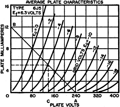
Fig. 2 - A set of average plate characteristics for a type
6J5 tube with a load-line representing a 20,000·ohm load superimposed.
(3) Let us stop for an instant and examine the results thus far. Having assumed
the two most extreme conditions - the tube first as an open circuit and then as
a short circuit - we have found, in the first case, a plate voltage of 240 volts
across the tube at zero plate current, and a plate current of 12 ma. with zero plate
voltage for the second assumption. Since the plate load is resistive, it follows
Ohm's law at all times, so that for any other assumptions which involve a partially
conducting tube between the two extremes, points must be located along a straight
line connecting A and B. This is an outcome of the linearity of a resistor in which
current and voltage are always directly proportional to each other. Thus, points
A and B are the terminals of the straight load line shown in Fig. 2, which
is unique for a 6J5 having a 20,000-ohm plate load and a supply voltage of 240 volts.
The examples that follow show how this load line is used.
Problem: Find the grid bias which permits 5 ma. of plate current to flow in a
6J5 having circuit constants as given. Solution: The load line intersects the 5-ma.
line on the -4 volt bias curve. Hence, a bias of -4 volts is just right if the plate
current is to be 5 ma. Moreover, if the intersection is brought down to the voltage
axis (C), it is seen that the plate voltage of the tube is now 140 volts. This means
that the voltage drop across the plate load resistor must be 100 volts. Note how,
by mere inspection, the load line provides information on the magnitude of the plate
current, the actual plate voltage, and the fall of potential along the load resistor.
Problem: If this tube is run at zero bias, what is its actual plate voltage?
Solution: Locate the intersection of the load line with the zero bias curve. This
occurs at a plate current of 8 ma. Moving down along the vertical line at the intersection,
we cross the plate voltage axis at 80 volts - the true plate voltage; the remaining
160 volts is the drop across the load resistor.
Problem: A relay having a 10,000-ohm coil is used as a plate
load in series with a 10,000-ohm resistor. If its pull-in current is 2 ma., what
grid bias is required to activate its armature? Solution: The relay, together with
the series resistor, constitutes a plate load of 20,000 ohms for which this load
line has been drawn. The load line crosses the 2-ma. marker halfway between the
-8 and -10 volt bias curves. Thus, a bias voltage of -9 volts will be just right
for pull-in. With these circuit constants, the voltage across the tube is 200 volts
and the potential applied to the series combination is 40 volts.
Load lines are very useful in predicting stage gain on the basis of static curves
since they permit the determination of output voltage swing as compared with input
voltage variations. (See After Class, December, 1955). Using the methods outlined
above, simply draw the appropriate load line for the particular tube and load resistor,
and find the voltage drop across the plate load resistor for the two extremes of
signal input. The difference between the output potentials is the output swing which
may then be compared with the input swing to determine the gain.
Load Line Quiz

Fig. 3 - Average plate characteristics of triode section
of a 6AQ6 for use in quiz.
Answer the following questions for a circuit using the triode section of a 6AQ6
double-diode high-mu triode having a 300-volt plate supply and a load resistor of
50,000 ohms. Curves for the 6AQ6 are given to the right in Fig. 3.
1. Find points A and B for the construction of the load line (Fig. 2 indicates
which points these are).
2. What grid bias is required to obtain a 50-volt drop across the load resistor?
3. What plate current in ma. flows during the quiescent period when the drop
across the tube is 150 volts?
4. What grid bias in volts is needed to bring about the conditions described
in question No.3?
5. What Is the voltage drop across the plate load resistor when the tube
operates at zero bias?
Answers at bottom.
"After Class" Topics
Load Line Quiz Answers
1. Point A falls on 300 volts on the plate voltage axis; point B is the
6-ma. marker on the plate current axis.
2. -3 volts.
3. 3 ma.
4. -0.3 volts, approx.
5. 170 volts, approx.
Posted October 13, 2023
(updated from original post
on 11/25/2014)
|