

RF Cascade Workbook for Excel
RF & Electronics Symbols for Visio
RF & Electronics Symbols for Office
RF & Electronics Stencils for Visio
RF Workbench
T-Shirts, Mugs, Cups, Ball Caps, Mouse Pads
Espresso Engineering Workbook™
Smith Chart™ for Excel
|
 |
RF Cascade Workbook© 2005 User's Guide - Chapter 4 |
|
Chapter 1,
2,
3,
4,
5,
6,
7,
8,
9,
10,
11,
12,
13
Version 1.11 by Kirt Blattenberger
RF Cafe Website (www.rfcafe.com)
Chapter 4
4
Device Specification
Each device is
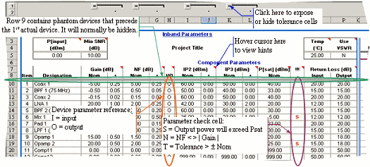
specified similar to what is shown in Table 3. Figure 5 identifies
each of the special features in the worksheet, so please review
it carefully before proceeding. Note that device parameter input
cells from RF Cascade Workbook 2003 may be copied and pasted
into this version, provided that care is taken to not paste
over formula cells (white backgrounds). Noise Bandwidth values
are now entered on the “Filter-Mixer” worksheet rather than
on the “Inband” worksheet. All cell input data is validated
for correctness.
|

|
|
Figure 5 Device
Specification Input Area
|
A description of
and allowable input range for each device parameter is given
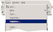
in Table 3. Limits have been set using the “Data->Validation”
menu selection (Figure 6), and may be changed by the user. Keep
in mind if you decide to increase the limits on dB values (although
it is hard to imagine why the need would arise) that the VBA
functions use double precision numbers with a maximum value
of around 10308, so values like NF, IP2 and IP3 that
need to be converted from decibels to linear numbers during
calculation could exceed the limit and cause an error to display
in the cells. Cell contents are validated using the built in
Excel data validation feature (use Validation… menu to modify). |
|

|
|
Figure 6 Data
Validation Menu Access
|
|
Parameter
|
Description
|
Range
|
Tolerance
|
Units
|
Designation |
Descriptive name |
-
|
-
|
-
|
Gain |
Linear power Gain |
-1000 to +1000
|
-1000 to +1000
|
dB
|
NF |
Noise Figure |
0 to +1000
|
0 to +1000
|
dB
|
I/O |
Input/Output parameter
reference – applies only to IP2 and IP3. Conversion
of the input value is not made automatically by switching
between “I” and “O,” so entering +20 dBm as the IIP3
(with an “I” in the “I/O” cell) and then changing to
an “O” will result in the +20 dBm being interpreted
as the OIP3. Make the conversions as follows:OIP2(3)
= IIP2(3) + GainIIP2(3) = OIP2(3) - Gain |
“i” or “I” forinput
“o” or “O” for output
|
-
|
-
|
IP2 |
2nd-Order Intercept
Point |
-1000 to +1000
|
-1000 to +1000
|
dBm
|
IP3 |
3rd-Order Intercept
Point |
-1000 to +1000
|
-1000 to +1000
|
dBm
|
P[sat] |
Saturated Power |
-1000 to +1000
|
-1000 to +1000
|
dBm
|
!!!(this is
not an input) |
Displays
alert for the following conditions:N = A negative
value is entered in the Gain cell, but the NF
is not equal to the absolute value of the Gain. S
= The input power plus linear Gain results in an output
power greater than the saturated power for the device.
P[sig]max power is used for testing worst case. T
= Tolerance exceeded on any of the following |
>
| ±Gain÷2, > | ±NF÷2 |, > |
±IP2÷2 |, > | ±IP3÷2 |
|
-
|
-
|
Input Return Loss |
RL =
 |
10-3 to 50
|
-
|
dB
|
Output Return
Loss |
RL =
 |
10-3 to 50
|
-
|
dB
|
|
|
Table 3 Device
Input Parameters
|
|
Chapter 1,
2,
3,
4,
5,
6,
7,
8,
9,
10,
11,
12,
13
|
Version 1.11 by Kirt Blattenberger
RF Cafe Website (www.rfcafe.com)
|
Chapter 4
|
|
 |
|


 |


