|
Chapter
1, 2,
3, 4,
5, 6,
7, 8,
9,
10, 11,
12,
13
Version 1.11 by Kirt Blattenberger RF Cafe Website (www.rfcafe.com)
Chapter 9
9 Filter-Mixer
Plots
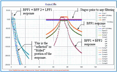
By default, all 24 stages are plotted on the “Mixer-LO Plot” worksheet, as shown in Figure 16. Unused stages
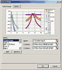
can easily be removed by right-clicking in the plot area and selecting the “Source Data…” option. The resulting
dialog window is shown in Figure 17. Note that because the LO (75 MHz) is inside the total calculated band (50-100
MHz), part (half in this case) of the response is “reflected” or “folded” about the 0 Hz axis.
|

|
|
Figure 16 Filter-Mixer
Plot
|
|

|
|
Figure 17 Source Data Configuration Window
|
|
Chapter
1, 2,
3, 4,
5, 6,
7, 8,
9,
10, 11,
12,
13
|
Version 1.11 by Kirt Blattenberger RF Cafe Website (www.rfcafe.com)
|
Chapter 9
|
|


