

RF Cascade Workbook for Excel
RF & Electronics Symbols for Visio
RF & Electronics Symbols for Office
RF & Electronics Stencils for Visio
RF Workbench
T-Shirts, Mugs, Cups, Ball Caps, Mouse Pads
Espresso Engineering Workbook™
Smith Chart™ for Excel
|
 |
RF Cascade Workbook© 2005 User's Guide - Chapter 8 |
|
Chapter
1, 2,
3, 4,
5, 6,
7, 8,
9,
10, 11,
12,
13
Version 1.11 by Kirt Blattenberger RF Cafe Website (www.rfcafe.com)
Chapter 8
8 Mixers + LOs
Ideal mixers use two input signals to generate sum and difference frequencies at
the output. One signal is the input frequency to be converted (commonly referred to as the RF) and the other
is a local oscillator (referred to as the LO) that is higher or lower infrequency than the input signal by an
amount equal to the difference between the input frequency and the desired output frequency. See Figure 14. RF
Cascade Workbook 2005 uses only the sideband (upper or lower) that you specify when calculating results. It
does not account for the unintended sideband (see section 5.2 for discussion on image noise).
| |

|

|
|
Figure 14 Mixer/LO
Configuration & Equation
|
|
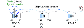
A unique pictorial presentation of what happens during frequency translation is
provided in Figure 15. All four combinations of the mixing equation shown in Figure 14 are covered. Figures A
and B are equivalent results for both the LO-RF and the RF-LO cases. In case A, the subtraction results in
negative frequencies, but the negative terms are said to be “reflected” or “folded” about the 0 Hz (DC) axis.
The subtraction in case B does not produce any negative results, so there is no need to mathematically reflect
is about 0 Hz. There is no real physical reflection mechanism occurring, it is merely a mathematical
convenience. The mixer has no way of determining which frequency is being subtracted from the other,
regardless of you happen to write the equation.
|
|
No spectral inversion occurs in either the upper sideband (USB) or the lower
sideband (LSB) with a low-side LO injection (cases A and B). However, with a high-side LO injection, the LSB
will exhibit spectral inversion while the USB does not (cases C, D and E). An explanation of spectral
inversion is provided in the next paragraph. First, though, note that with a high-side LO there is an
equivalent subtraction/reflection pair similar to the low-side LO case. Case E is a special case where the LO
functions as both a low-side and a high-side signal. There, a portion of the band experiences spectral
inversion while the other portion does not.
|
|

|
|

|
|

|
|

|
|

|
|
Figure 15 Frequency
Inversion
|
Spectral Inversion |
|
Spectral inversion occurs when the lower sideband of a high-side injected LO is
used for the output, like the examples in Figure 15 C, D and E. The result is the lower frequencies of the
input band being translated into the upper frequencies of the output band, and vice versa. Shading and
arrow-tipped lines are used to track the relative band edges. A second inversion will cancel out the original,
but a third will reintroduce the inversion, and so on. Digital systems can un-invert the spectral inversion in
software or firmware if it knows to expect it. However, spectral inversion of analog voice information results
in unintelligible garble.
|
|
Translated frequencies are calculated and stored for every component at every
input frequency (76 frequency as the default value). Refer to Figure 12 to see how the frequency range shifts
at the output of the mixer (Mix 1) stage. If more than one mixer is used, then the frequency range s will
shift accordingly each time based on the LO frequency and chosen sideband.
|
|
Chapter
1, 2,
3, 4,
5, 6,
7, 8,
9,
10, 11,
12,
13
|
Version 1.11 by Kirt Blattenberger RF Cafe Website (www.rfcafe.com)
|
Chapter 8
|
|
 |
|


 |


