Module 16 - Introduction to Test Equipment
Pages i,
1-1,
1-11,
1-21,
2-1,
2-11,
2-21,
3-1,
3-11,
3-21,
3-31,
4-1,
4-11,
4-21,
5-1,
5-11,
5-21,
5-31,
6-1,
6-11,
6-21,
6-31,
6-41, Index
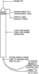
Figure 5-17. - Basic logic probe. The logic probe can be powered from the supply of the circuit under test or from a regulated dc power
supply. If a separate power supply is used, the ground points of the power supply and circuit under test should be
connected together. The display LED (light-emitting diode) near the probe tip provides an immediate
indication of the logic state existing in the circuit under test. The LED will provide any of four indications:
(1) off, (2) dim (about one-half brilliance), (3) bright (full brilliance), and (4) flashing on and off. The LED
is normally in the dim state and must be driven to one of the other three states by voltage levels at the probe
tip. The LED is usually bright for inputs above the logic "1" threshold and off for inputs below the logic "0"
threshold. The LED is usually dim for voltages between the logic "1" and logic "0" thresholds and for open
circuits. Q-7. The LED lamps of a typical logic probe are normally in what state? Another logic
circuit analysis technique is useful with the logic probe. This technique is to run the circuit under test at its
normal clock (timing) rate while monitoring for various control signals, such as RESET, START, STOP, SHIFT,
Transfer, or CLOCK. Questions such as "Is the counter operating?" are quickly resolved by noting if the probe
indicator is flashing on and off, indicating that pulse train activity is present.
This ends our discussion on logic probes. Now, we'll study another piece of electronics test
equipment that is used in evaluating integrated circuits, the HUNTRON TRACKER 2000.
5-21
HUNTRON TRACKER 2000 The logic probe we just discussed is but one specialized tool used to isolate problems to the component
level. Another device you can use is the Huntron Tracker 2000. It is a very versatile electronic troubleshooting
tool that is used to evaluate suspect components and/or locate defective components on de-energized circuit
cards quickly and safely without requiring the removal of component leads. The unit provides a built-in display
that allows you to visually analyze the component under test conditions.
Caution Before connecting the Huntron Tracker 2000, you must
first secure all power, then discharge all high-voltage capacitors. PHYSICAL FEATURES Because the Tracker 2000 has so many controls and indicators,
it would impractical to cover each within this chapter. We will therefore concentrate our discussion only to the
externally accessible features. To find information on internal controls and indicators, you should review the
most current technical manual with up-to-date changes entered for the unit being used. Front
Panel
The front-panel (figure 5-18) design allows you to easily select the desired function. All the push buttons are
the momentary action type and have light-emitting diode (LED) indicators embedded in them to show the functions
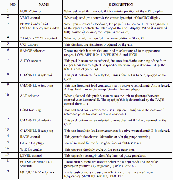
that are active, by lighting up when active. a detailed description of each item on the front panel is provided in
table 5-3.
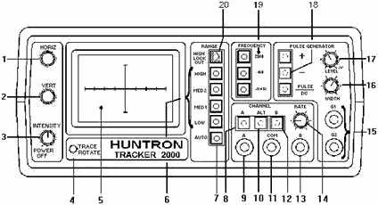
Figure 5-18. - Front Panel.
5-22
Table 5-3. - Front-Panel Controls and Connectors
 Cathode-Ray Tube (CRT) Display The CRT display (figure 5-19) is used to view
the signature of the component under test. The display has a graticule consisting of a horizontal and vertical
axes. The horizontal axis is used to represent voltage with the vertical axis being used to represent current. The
axes divide the display into four quadrants. Each quadrant displays a different portion of the signature for the
component under test.
5-23
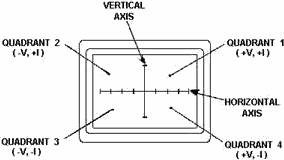
Figure 5-19. - CRT display.
· Quadrant 1 displays positive voltage and positive current.
· Quadrant 2
displays negative voltage and positive current.
· Quadrant 3 displays negative voltage and
negative current.
· Quadrant 4 displays positive voltage and negative current.
Q-8. On the CRT display, what information is displayed in Quadrant 4?
The horizontal axis (see figure 5-19) is divided into eight equal divisions, allowing the technician to
estimate the voltage at which changes occur in the signature for the component being tested. The associated
approximate horizontal sensitivities for each range are:
· High = 15.0 Volts/Div.
· Medium 2
= 5.0 Volts/Div.
· Medium 1 = 3.75 Volts/Div.
· Low = 2.5 Volts/Div.
Back Panel The back panel (figure 5-20) provides three additional controls and
connectors. One is the accessory output connector (ACC), which provides a clock signal and power for the Huntron
Switcher Model HSR410. Next, is the power cord connector used to provide the required ac line voltage used to
power the unit. The last item found on the back panel is the FOCUS control; this controls the focus for the front-
panel CRT display.
5-24
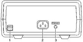
Figure 5-20. - Back panel. Operation The following sections explain how to use most of the front- and
back-panel controls and connectors. Each control and connector has already been briefly described. To review this
information, refer to figure 5-18 and table 5-3. Initial Setup First, turn
the Power/INTENSITY knob located on the front panel to the clockwise, on, position. Under normal conditions, the
unit will come on with the following LEDs illuminated: power, channel A, 50/60 Hz, low range, and pulse/DC.
Focusing the CRT is very critical for the technician to be able to properly analyze the signature being
displayed. This is done by first turning the INTENSITY control to a level comfortable for the eye, and then
adjusting the FOCUS control (back panel) for the narrowest possible trace. Aligning the trace will help
determine, during troubleshooting, which quadrant the portion of the signature is in during a change. With a short
circuit applied to channel a (connect a cable between jack a and COM), adjust the TRACE ROTATE control until the
trace is as close to parallel as possible to the vertical axis. Then, adjust the HORIZ (horizontal) control until
the vertical trace is as close to even with the vertical axis as possible. Q-9. When aligning the trace
with a short applied to channel A, which control should be adjusted to bring the trace parallel to the vertical
axis?
With an Open applied to channel a (nothing connected to a and COM test plug), adjust the VERT (vertical) control
until the horizontal trace is as close to even with the horizontal axis as possible. Once set, these adjustments
should not need readjusting during the unit's operation. However, remember that each time the unit is used, this
process will need to be repeated. Range Selection Four impedance ranges (Low,
MED 1, MED 2, and High) can be selected on the Tracker 2000. These ranges will become active when the appropriate
front-panel button is pressed. To obtain the most useful signature display when troubleshooting a component, you
should always start by selecting one of the two medium ranges (medium 1 or medium 2). If the display appears to be
an open (horizontal trace), then the next higher range should be selected to get a more accurate signature for
analysis. If the display appears to be a short (vertical trace), then the next lower range should be selected.
5-25
The AUTO feature, when selected, will allow the unit to automatically scan through the four ranges at
a speed set by the technician using the RATE control knob. This allows the user to keep his or her hands free to
hold test leads while still being able to observe the component under test signature for analysis. The High
LOCKOUT, when selected by the technician, prevents the unit from functioning in the High range in either the
manual or AUTO mode.
Channel Selection You can select two channels by pressing the channel a (test
probes connected to a jack and COM) or channel B (test probes connected to B and COM jacks) push button on the
front panel. When using a single channel, you should plug the red probe into the corresponding channel test jack,
and plug the black test lead into the common test jack. When testing a component, you should connect the red probe
to the positive terminal and the black probe to the negative terminal of the component under test. Following this
procedure every time will ensure that the signature for the component under test will be displayed in the correct
quadrants of the CRT display. The ALT (alternate) mode provides automatic switching back and forth
between channel a and channel B. This allows you to easily compare two components or the same test points on two
circuit boards. You select the ALT mode by pressing the ALT push button on the front panel. The rate of switching
between channels a and B can be varied by adjusting the RATE control knob on the front panel. You will find that
the ALT mode feature is very useful for comparing a known good component with the same type of component that is
of unknown quality.
Figure 5-21 shows a typical way of connecting the unit to a known good circuit board and a board under
test. This test mode uses the supplied common test leads to connect two equivalent points on the boards to the
common test jack. Note that the black probe is now being used in the channel B jack rather than the COM jack. When
the technician uses the ALT and AUTO features together, each channel is displayed before the range selection will
change. Figure 5-22 shows the sequence of these changes.

Figure 5-21. - ALT (alternate) mode setup.
5-26
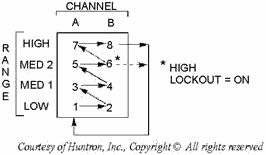
Figure 5-22. - AUTO/ALT sequence. Frequency Selection There are three test signal frequencies (50/60 Hz, 400 Hz,
and 2000 Hz) that can be selected and then provided by pressing the appropriate front-panel push button. During
most troubleshooting evolutions, the 50/60 Hz test signal is the best to start with. The 400 Hz and 2000 Hz
frequencies are generally used to view small amounts of capacitance or large amounts of inductance.
Pulse Generator A built-in pulse generator is also provided with the Tracker 2000. It allows the
technician to do dynamic, in-circuit testing of certain devices in their active mode. In addition to using the red
and black probes, you can connect the output of the pulse generator to the control input of the device to be
tested with one of the blue micro clips provided with the unit. The pulse generator has two outputs (G1 and G2
jacks) so that three devices can also be tested in the ALT (alternate) mode. Figure 5-23 shows a way of connecting
the unit in the ALT mode using the pulse generator.

Figure 5-23. - Pulse generator comparison mode. There are a variety of output waveforms available using the pulse generator selection buttons, as shown
in figure 5-24. First, the technician must select the PULSE mode or DC mode using the PULSE/DC button located on
the front panel. In the PULSE mode, the PULSE/DC LED flashes at a slow rate. While in the DC mode, this LED will
be continuously on.
5-27
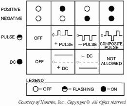
Figure 5-24. - Pulse generator selector chart. Next, the technician needs to select the polarity of the output desired by using the positive (+) and/or
negative (-) push buttons. All three buttons only function in a push-on/push-off mode and will only interact with
each other to avoid the NOT ALLowED state found in figure 5-24. Once the specific output type has been
selected, the output desired by the technician is set using the LEVEL and WIDTH controls. The LEVEL control is used to vary the magnitude of the output amplitude from zero to 5 volts (peak or DC). During the PULSE mode, the
WIDTH control will adjust the cycle of the pulse output from low to 50 percent maximum (square wave). The
start of a pulse will be triggered by the appropriate zero crossing of the test signal, which results in the pulse
frequency being equal to the selected test signal frequency. The end of the pulse is determined by the
WIDTH control setting, which determines the cycle length. The WIDTH control, however, has no effect when the DC
mode is selected. FunctionAL OVERVIEW There are six major sections in the
Tracker 2000, as shown in the block diagram in figure 5-25. The control logic section controls the selection of
the channel, frequency, impedance range, and pulse generator mode according to the front-panel buttons pushed by
the technician. The oscillator provides the test signal that is used by the signal and pulse generator sections.
In the signal section, the test jacks are driven by the test signal, while signal conditioners monitor the jacks
and produce the horizontal and vertical signals used by the CRT section to produce a component signature on the
display. The pulse generator provides an added source for testing three additional terminal devices. The power
supply produces all the required voltages needed to operate the Tracker 2000.
5-28
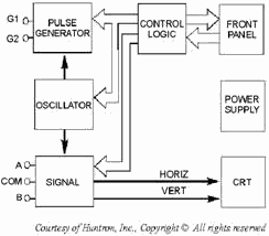
Figure 5-25. - Tracker 2000 block diagram. Control Logic The control logic senses which button is pushed on the front
panel. Since the buttons are the momentary action type, the logic must remember what button was pushed, turn on
the LED indicator within the button, and activate the appropriate configuration of the oscillator, signal, and
pulse generator sections. After a button is pushed, the unit will remain in that configuration until
another selection is made or the power is secured. The High LOCKOUT and PULSE GENERATOR push buttons are the only
ones that require repetitive pressing to be turned on or off. The channel relay is controlled by CHANNEL
buttons A, ALT, and B. The relay is a single-pole, double-throw type and is de-energized for channel a and
energized for channel B. If CHANNEL a is already selected and the CHANNEL B button is pressed, CHANNEL a will be
canceled and CHANNEL B selected. When the ALT button is pressed, another control line is set, which enables an
internal clock to toggle the channel relay on and off, causing the unit to alternate between channels a and B.
The internal clock is controlled by the RATE control knob on the front panel. When the ALT mode is active,
the LEDs within the a and B buttons flash alternately, and the ALT LED is on continuously. Pressing either of the
channel buttons will cancel the ALT mode, and the selected channel will then become active. The Frequency
buttons (50/60, 400, and 2000 Hz) directly control the operation of the oscillator and the pulse generator. The
RANGE buttons (Low, MED 1, MED 2, and High) control four relays in the signal section that select the appropriate
terminal characteristics for each impedance range (table 5-4).
5-29
Table 5-4. - Terminal Characteristics for Impedance ranges
 You can select the four ranges manually by pressing the RANGE button, or you can scan them automatically
by using the AUTO function. When AUTO is activated, the control logic will follow the sequence Low, MED 1, MED 2,
and High over and over if High LOCKOUT is off. The current active range is always indicated by the LED for the
range selected. The AUTO mode will stay active until you select a particular range by pressing its associated
button. While AUTO is active, the AUTO LED is continuously on. The speed at which the ranges are scanned
is controlled by the front-panel RATE control knob. This allows you to adjust the time each range is displayed for
signature analysis on the CRT display. If AUTO and ALT (alternate) are active at the same time, the RATE control
affects the speed of both functions with ALT having priority. This is done so that the two channels can be
compared to each other within one range before the next range is selected (figure 5-26).
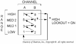
Figure 5-26. - Range scanning sequence with AUTO and ALT active. The High LOCKOUT function disables the High range and limits the maximum test signal to 20 volts peak
vice 60 volts peak. When you select the manual mode (AUTO off), activating the High LOCKOUT prevents the High
range from being selected. If the High range is active when the High LOCKOUT is pressed, the High range is
canceled and the next lower range (MED 2) will be selected and become active. When you select the AUTO mode, the
RANGE sequence with the High LOCKOUT active will start with Low, and sequence through MED 1, MED 2, back to Low,
and continue until the AUTO mode is stopped. The PULSE GENERATOR buttons (positive [+], negative [-], and
PULSE/DC) toggle control lines that change the polarity and output type of the pulse generator.
5-30
| - |
Matter, Energy,
and Direct Current |
| - |
Alternating Current and Transformers |
| - |
Circuit Protection, Control, and Measurement |
| - |
Electrical Conductors, Wiring Techniques,
and Schematic Reading |
| - |
Generators and Motors |
| - |
Electronic Emission, Tubes, and Power Supplies |
| - |
Solid-State Devices and Power Supplies |
| - |
Amplifiers |
| - |
Wave-Generation and Wave-Shaping Circuits |
| - |
Wave Propagation, Transmission Lines, and
Antennas |
| - |
Microwave Principles |
| - |
Modulation Principles |
| - |
Introduction to Number Systems and Logic Circuits |
| - |
- Introduction to Microelectronics |
| - |
Principles of Synchros, Servos, and Gyros |
| - |
Introduction to Test Equipment |
| - |
Radio-Frequency Communications Principles |
| - |
Radar Principles |
| - |
The Technician's Handbook, Master Glossary |
| - |
Test Methods and Practices |
| - |
Introduction to Digital Computers |
| - |
Magnetic Recording |
| - |
Introduction to Fiber Optics |
| Note: Navy Electricity and Electronics Training
Series (NEETS) content is U.S. Navy property in the public domain. |
|


