Module 18 - Radar PrinciplesPages
i,
1-1, 1-11,
1-21,
1-31,
1-41,
2-1,
2-11,
2-21,
2-31,
2-41,
3-1,
3-11,
3-21,
4-1,
4-11,
4-21,
AI-1,
AII-1,
Index-1 to 3
≡
≡ ≡
≡ ≡
≡ ≡
≡ ≡
≡ ≡
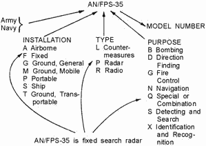
Table 1-1. - Table of Equipment Indicators
| TABLE of Equipment INDICATORS |
Miscellaneous Identification |
| Installation (1st letter) |
Type of Equipment (2d letter) |
Purpose (3rd letter) |
|
| A - Piloted aircraft B - Underwater mobile, submarine D - Pilotless carrier F - Fixed ground G - General ground use K - Amphibious M - Ground, mobile P - Portable S - Water T - Ground, transportable U - General utility V - Ground,
vehicular W - Water surface and under water combination Z - Piloted and pilotless airborne vehicle combination |
A - invisible light, heat radiation C - Carrier D - Radiac G - Telegraph or
Teletype
I - Interphone and public address J - Electromechanical or Inertial wire covered K - Telemetering
L - Countermeasures M - Meteorological N - Sound in air P - Radar Q - Sonar and underwater sound R - Radio S - Special types, magnetic, etc., or combinations of types
T - Telephone (wire) V - Visual and visible light W - Armament (peculiar to armament, not
otherwise covered)
X - Facsimile or television Y - Data processing |
B - Bombing C - Communications (receiving and transmitting D - Direction finder
reconnaissance and/or surveillance E - Ejection and/or release G - Fire control, or search- light
directing H - Recording and/or reproducing (graphic meteorological and sound) K - Computing
M - Maintenance and/or test assemblies (including tools) N - Navigational aids (including altimeters,
beacons, compasses, racons, depth sounding, approach and landing) Q - Special, or combination of
purposes R - Receiving, passive detecting S - Detecting and/or range and bearing, search T - Transmitting W - Automatic flight or remote control X - Identification and recognition Y - Surveillance (search
detect, and multiple target tracking) and control (both fire control and air control) X - Facsimile or
television |
X, Y, Z - Changes in voltage, phase, or frequency T - Training (V) - Variable grouping
|
1-31

Figure 1-23. - Joint service classification system. Radar Functions No single radar system has yet been designed that can perform all of the
many radar functions required by the military. Some of the newer systems combine several functions that formerly
required individual radar systems, but no single system can fulfill all the requirements of modern warfare. As a
result, modern warships, aircraft, and shore stations usually have several radar systems, each performing a
different function.
One radar system, called SEARCH Radar, is designed to continuously scan a volume of space to provide
initial detection of all targets. Search radar is almost always used to detect and determine the position of new
targets for later use by TRACK Radar. Track radar provides continuous range, bearing, and elevation data on one or
more targets. Most of the radar systems used by the military are in one of these two categories, though the
individual radar systems vary in design and capability. Some radar systems are designed for specific functions
that do not precisely fit into either of the above categories. The radar speed gun is an example of radar designed
specifically to measure the speed of a target. The military uses much more complex radar systems that are adapted
to detect only fast- moving targets such as aircraft. Since aircraft usually move much faster than weather or
surface targets, velocity-sensitive radar can eliminate unwanted clutter from the radar indicator. Radar systems
that detect and process only moving targets are called MOVING-TARGET INDICATORS (mti) and are usually combined
with conventional search radar. Another form of radar widely used in military and civilian aircraft is the
Radar ALTIMETER. Just as some surface-based radars can determine the height of a target, airborne radar can
determine the distance from an aircraft to the ground. Many aircraft use radar to determine height above the
ground. Radar altimeters usually use frequency-modulated signals of the type discussed earlier in the chapter. 1-32
Radar TYPES The preceding paragraphs indicated that radar systems are divided into types based on the designed use. This
section presents the general characteristics of several commonly used radar systems. Typical characteristics are
discussed rather than the specific characteristics of any particular radar system. SEARCH Radar Search radar, as previously mentioned, continuously scans a volume of space
and provides initial detection of all targets within that space. Search radar systems are further divided into
specific types, according to the type of object they are designed to detect. For example, surface-search,
air-search, and height-finding radars are all types of search radar. Surface-Search Radar
a surface-search radar system has two primary functions: (1) the detection and determination of accurate ranges
and bearings of surface objects and low-flying aircraft and (2) the maintenance of a 360- degree search pattern
for all objects within line-of-sight distance from the radar antenna. The maximum range ability of
surface-search radar is primarily limited by the radar horizon; therefore, higher frequencies are used to permit
maximum reflection from small, reflecting areas, such as ship masthead structures and the periscopes of
submarines. Narrow pulse widths are used to permit a high degree of range resolution at short ranges and to
achieve greater range accuracy. High pulse-repetition rates are used to permit a maximum definition of detected
objects. Medium peak power can be used to permit the detection of small objects at line-of-sight distances. Wide
vertical-beam widths permit compensation for the pitch and roll of own ship and detection of low flying aircraft.
Narrow horizontal- beam widths permit accurate bearing determination and good bearing resolution. For example, a
common shipboard surface-search radar has the following design specifications: • Transmitter frequency
5,450-5,825 MHz • Pulse width .25 or 1.3 microseconds • Pulse-repetition rate between 625 and 650
pulses per second • Peak power between 190 and 285 kW • Vertical beam width between 12 and 16
degrees • Horizontal beam width 1.5 degrees Surface-search radar is used to detect the presence of
surface craft and low flying aircraft and to determine their presence. Shipboard surface-search radar provides
this type of information as an input to the weapons system to assist in the engagement of hostile targets by
fire-control radar. Shipboard surface- search radar is also used extensively as a navigational aid in coastal
waters and in poor weather conditions. a typical surface-search radar antenna is shown in figure 1-24. 1-33

Figure 1-24. - Surface-search radar.
Q32. What type of radar provides continuous range, bearing, and elevation data on an object? Q33.
Radar altimeters use what type of transmission signal? Q34. a surface-search radar normally scans how many
degrees of azimuth? Q35. What limits the maximum range of a surface-search radar? Q36. What is the
shape of the beam of a surface-search radar? Air-Search Radar Air-search radar
systems initially detect and determine the position, course, and speed of air targets in a relatively large area.
The maximum range of air-search radar can exceed 300 miles, and the bearing coverage is a complete 360-degree
circle. Air-search radar systems are usually divided into two categories, based on the amount of position
information supplied. As mentioned earlier in this chapter, radar sets that provide only range and bearing
information are referred to as two-dimensional, or 2D, radars. Radar sets that supply range, bearing, and height
are called three-dimensional, or 3D, radars. (3D radar will be covered in the next section.) The coverage pattern
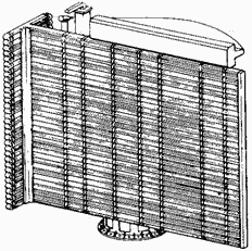
of a typical 2D radar system is illustrated in figure 1-25. a typical 2D air-search radar antenna is shown in
figure 1-26.

Figure 1-25. - 2D radar coverage pattern. 1-34

Figure 1-26. - 2D air-search radar. Relatively low transmitter frequencies are used in 2D search radars to permit long-range transmissions with
minimum attenuation. Wide pulse widths and high peak power are used to aid in detecting small objects at great
distances. Low pulse-repetition rates are selected to permit greater maximum range. a wide vertical-beam width is used to ensure detection of objects from the surface to relatively high altitudes and to compensate for pitch and
roll of own ship. The output characteristics of specific air-search radars are classified; therefore, they will
not be discussed.
Air-search radar systems are used as early-warning devices because they can detect approaching enemy
aircraft or missiles at great distances. In hostile situations, early detection of the enemy is vital to a
successful defense against attack. Antiaircraft defenses in the form of shipboard guns, missiles, or fighter
planes must be brought to a high degree of readiness in time to repel an attack. Range and bearing information,
provided by air-search radars, used to initially position a fire-control tracking radar on a target. Another
function of the air-search radar system is guiding combat air patrol (CAP) aircraft to a position suitable to
intercept an enemy aircraft. In the case of aircraft control, the guidance information is obtained by the radar
operator and passed to the aircraft by either voice radio or a computer link to the aircraft.
Height-Finding Search Radar The primary function of a height-finding radar (sometimes referred to as
a three-coordinate or 3D radar) is that of computing accurate ranges, bearings, and altitudes of aircraft targets
detected by air- search radars. Height-finding radar is also used by the ship's air controllers to direct CAP
aircraft during interception of air targets. Modern 3D radar is often used as the primary air-search radar (figure
1-27). This is because of its high accuracy and because the maximum ranges are only slightly less than those
available from 2D radar. 1-35

Figure 1-27. - 3D air-search radar. The range capability of 3D search radar is limited to some extent by an operating frequency that is higher
than that of 2D radar. This disadvantage is partially offset by higher output power and a beam width that is
narrower in both the vertical and horizontal planes. The 3D radar system transmits several narrow beams to
obtain altitude coverage and, for this reason, compensation for roll and pitch must be provided for shipboard
installations to ensure accurate height information. Applications of height-finding radars include the
following: • Obtaining range, bearing, and altitude data on enemy aircraft and missiles to assist in
the control of CAP aircraft • Detecting low-flying aircraft • Determining range to
distant land masses • Tracking aircraft over land • Detecting certain weather phenomena •
Tracking weather balloons • Providing precise range, bearing, and height information for fast, accurate
initial positioning of fire-control tracking radars
Q37. Air-search radar is divided into what two basic categories? Q38. What position data are
supplied by 2D search radar? Q39. Why do 2D air-search radars use relatively low carrier frequencies and
low pulse-repetition rates? Q40. Why is the range capability of 3D radar usually less than the range of
2D radar?
1-36
TRACKING Radar Radar that provides continuous positional data on a target is
called tracking radar. Most tracking radar systems used by the military are also fire-control radar; the two names
are often used interchangeably. Fire-control tracking radar systems usually produce a very narrow,
circular beam.
Fire-control radar must be directed to the general location of the desired target because of the
narrow-beam pattern. This is called the DESIGNATION phase of equipment operation. Once in the general vicinity of
the target, the radar system switches to the ACQUIsITION phase of operation. During acquisition, the radar system
searches a small volume of space in a prearranged pattern until the target is located. When the target is located,
the radar system enters the TRACK phase of operation. Using one of several possible scanning techniques, the radar
system automatically follows all target motions. The radar system is said to be locked on to the target during the
track phase. The three sequential phases of operation are often referred to as Modes and are common to the
target-processing sequence of most fire- control radars. Typical fire-control radar characteristics
include a very high prf, a very narrow pulse width, and a very narrow beam width. These characteristics, while
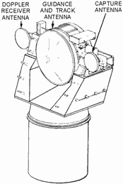
providing extreme accuracy, limit the range and make initial target detection difficult. a typical fire-control
radar antenna is shown in figure 1-28. In this example the antenna used to produce a narrow beam is covered by a
protective radome.

Figure 1-28. - Fire-control radar. MIsSILE-GUIDANCE Radar A radar system that provides information used to guide a missile
to a hostile target is called GUIDANCE Radar. Missiles use radar to intercept targets in three basic ways: (1)
Beam-rider missiles 1-37
follow a beam of radar energy that is kept continuously pointed at the desired target; (2) homing
missiles detect and home in on radar energy reflected from the target; the reflected energy is provided by a radar
transmitter either in the missile or at the launch point and is detected by a receiver in the missile; (3) passive
homing missiles home in on energy that is radiated by the target. Because target position must be known at all
times, a guidance radar is generally part of, or associated with, a fire-control tracking radar. In some
instances, three radar beams are required to provide complete guidance for a missile. The beam- riding missile,
for example, must be launched into the beam and then must ride the beam to the target. Initially, a wide beam is
radiated by a capture radar to gain (capture) control of the missile. After the missile enters the capture beam, a
narrow beam is radiated by a guidance radar to guide the missile to the target. During both capture and guidance
operations, a tracking radar continues to track the target. Figure 1-29 illustrates the relationships of the three
different radar beams.

Figure 1-29. - Beam relationship of capture, guidance, and track beams.
Q41. Fire-control tracking radar most often radiates what type of beam? Q42. Tracking radar searches
a small volume of space during which phase of operation? Q43. What width is the pulse radiated by
fire-control tracking radar? Q44. Which beam of missile-guidance radar is very wide?
CARRIER-Controlled APPROACH (CCA) and Ground-Controlled APPROACH (GCA) Radar CARRIER-Controlled
APPROACH and Ground-Controlled APPROACH radar systems are essentially shipboard and land-based versions of the
same type of radar. Shipboard CCA radar systems are usually much more sophisticated systems than GCA systems. This
is because of the movements of the ship and the more complicated landing problems. Both systems, however, guide
aircraft to safe landing under conditions approaching zero visibility. By means of radar, aircraft are detected
and observed during the final approach and landing sequence. Guidance information is supplied to the pilot in the
form of verbal radio instructions, or to the automatic pilot (autopilot) in the form of pulsed control signals.
AIRBORNE Radar Airborne radar is designed especially to meet the strict space and weight limitations
that are necessary for all airborne equipment. Even so, airborne radar sets develop the same peak power as
shipboard and shore-based sets. 1-38
As with shipboard radar, airborne radar sets come in many models and types to serve many different
purposes. Some of the sets are mounted in blisters (or domes) that form part of the fuselage; others are mounted
in the nose of the aircraft. In fighter aircraft, the primary mission of a radar is to aid in the search,
interception, and destruction of enemy aircraft. This requires that the radar system have a tracking feature.
Airborne radar also has many other purposes. The following are some of the general classifications of airborne
radar: search, intercept and missile control, bombing, navigation, and airborne early warning.
Summary The following paragraphs summarize the important points of this chapter. Radar is an
electronic system that uses reflected electromagnetic energy to detect the presence and position of objects
invisible to the eye. TARGET POSITION is defined in reference to true north, the
horizontal plane, and the vertical plane. TRUE BEARING is the angle between true north and
the line of sight to the target, measured in a clockwise direction in the horizontal plane.
ELEVATION ANGLE
is the angle between the horizontal plane and the line of sight, measured in the vertical plane.
RANGE
is the distance from the radar site to the target measured along the line of sight. The concepts are illustrated
in the figure.

RANGE to any target can be calculated by measuring the time required for a pulse to travel to
a target and return to the radar receiver and by dividing the elapsed time by 12.36 microseconds. 1-39

The MINIMUM RANGE of a radar system can be calculated from the formula:

The Maximum RANGE of a pulse radar system depends on the CARRIER Frequency, PEAK Power,
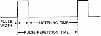
PULSE-REPETITION Frequency, and RECEIVER SENSITIVITY. PULSE-REPETITION TIME is the time
between the beginning of one pulse and the beginning of the next pulse and is the reciprocal of prf.
 
AMBIGUOUS RETurns are echoes from targets that exceed the prt of the radar system and
result in false range readings. The maximum (unambiguous) range for a radar system can be determined by the
formula:
 The PEAK Power of a radar system is the total energy contained in a pulse. Peak power is
obtained by multiplying the maximum power level of a pulse by the pulse width. Since most instruments are
designed to measure AVERAGE Power over a period of time, prt must be included in transmitter power measurements.
The formula for average power is: 1-40
| - |
Matter, Energy,
and Direct Current |
| - |
Alternating Current and Transformers |
| - |
Circuit Protection, Control, and Measurement |
| - |
Electrical Conductors, Wiring Techniques,
and Schematic Reading |
| - |
Generators and Motors |
| - |
Electronic Emission, Tubes, and Power Supplies |
| - |
Solid-State Devices and Power Supplies |
| - |
Amplifiers |
| - |
Wave-Generation and Wave-Shaping Circuits |
| - |
Wave Propagation, Transmission Lines, and
Antennas |
| - |
Microwave Principles |
| - |
Modulation Principles |
| - |
Introduction to Number Systems and Logic Circuits |
| - |
- Introduction to Microelectronics |
| - |
Principles of Synchros, Servos, and Gyros |
| - |
Introduction to Test Equipment |
| - |
Radio-Frequency Communications Principles |
| - |
Radar Principles |
| - |
The Technician's Handbook, Master Glossary |
| - |
Test Methods and Practices |
| - |
Introduction to Digital Computers |
| - |
Magnetic Recording |
| - |
Introduction to Fiber Optics |
| Note: Navy Electricity and Electronics Training
Series (NEETS) content is U.S. Navy property in the public domain. |
|


