Module 18 - Radar PrinciplesPages
i,
1-1, 1-11,
1-21,
1-31,
1-41,
2-1,
2-11,
2-21,
2-31,
2-41,
3-1,
3-11,
3-21,
4-1,
4-11,
4-21,
AI-1,
AII-1,
Index-1 to 3
Distilled water is one of the best mediums for cooling high-power components,
and, in many cases, the only medium that may be used.
For a distilled-water-cooling system to operate satisfactorily, the temperature,
quantity, purity, flow, and pressure of the water must be controlled. This control
is provided by various valves, regulators, sensors, meters, and instruments that
measure the necessary characteristics and provide the required regulation.
Liquid-cooling systems consist of a sea water or a chilled (fresh) water section
that cools the distilled water circulating through the electronic equipment. The
main components of cooling systems are piping, valves, regulators, heat exchangers,
strainers, circulating pumps, expansion tanks, gages, and demineralizers. Other
specialized components are sometimes necessary to monitor cooling water to the electronic
equipment.
A typical liquid-cooling system is composed of a PRIMARY Loop and a SECONDARY
Loop (figure 4-16). The primary loop provides the initial source of cooling water
and the secondary loop transfers the heat load from the electronic equipment to
the primary loop. The source of cooling water for the primary loop is either sea
water from a sea water supply or chilled water from the ship's air- conditioning
plant. The cooling water used in the secondary loop is distilled water. Ultrapure
systems are maintained by a demineralizer and use double-distilled water obtained
through the Navy Supply System.
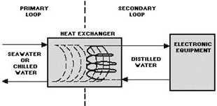
Figure 4-16. - Liquid cooling system block diagram.
Additional information about liquid cooling systems can be found in Basic Liquid
Cooling Systems for Shipboard Electronic Equipment Technician's Handbook, NAVSEA
0948-LP-122-8010.
Q19. What type of cooling is used to control ambient room temperature?
Q20. a typical liquid-cooling system is composed of what loops?
Q21. What loop of a cooling system is often supplied by sea water?
4-21
Safety
Many safety and health hazards are involved with operating and maintaining high-power
radars. These hazards result from high levels of RF radiation, X-ray emissions,
the necessity of working aloft, and the generation of extremely high voltages.
Navy professionals are very safety conscious and, as a result, the number of
accidents that occur on the job is small. Most of the safety precautions applicable
to radar are published in radar technical manuals. Many of the safety regulations
included in technical manuals are the result of actual experiences. Therefore, you
should give them careful thought and strict observance.
RF Radiation HAZARDS
Radar peak power may reach a million watts or more. RF radiation hazards exist
in the vicinity of radar transmitting antennas. These hazards are present not only
in front of an antenna but also to the sides and sometimes even behind it because
of spillover and reflection. At some frequencies, exposure to excessive levels of
radiation will not produce a sufficient sensation of pain or discomfort to warn
you of injury. If you suspect any injury, see your ship's doctor or corpsman. Be
sure to acquaint yourself with the actual radiation hazard zones of the radars on
your ship.
Personnel should observe the following precautions to ensure that persons are
not exposed to harmful RF radiation:
• Visual inspection of feedhorns, open ends of waveguides, and any other opening
that emits RF energy should not be made unless the equipment is properly secured
and tagged for that purpose.
• Operating and maintenance personnel should observe all RF radiation hazard
signs posted in the operating area.
• All personnel should observe RF radiation hazard (RADHAZ) warning signs (figure
4-17) that point out the existence of RF radiation hazards in a specific location
or area. (You may encounter other types of RF radiation hazard signs, depending
on the situation.)
• Ensure that radiation hazard warning signs are available and posted.
• Ensure that those radar antennas that normally rotate are rotated continuously
while radiating or are trained to a known safe bearing.
• Ensure that those antennas that do not normally rotate are pointed away from
inhabited areas
(ships, piers, and the like) while radiating.
• Dummy loads should be employed where applicable in transmitting equipment during
testing or checkout.
4-22

Figure 4-17. - Sample of one type of RADHAZ sign.
X-RAY EMIsSIONS
X rays may be produced by the high-voltage electronic equipment in radars. X
rays can penetrate human tissue and cause damage of a temporary or permanent nature.
Unless the dosage is extremely high, no ill effects will be noticeable for days,
weeks, or even years after the exposure.
The sources of these X rays are usually confined to magnetrons, klystrons, and
cathode-ray tubes. Personnel should not linger near any of these types of equipments
when the equipment covers have been removed. Klystrons, magnetrons, rectifiers,
or other tubes that employ an excitation of 15,000 volts or more may emit X rays
out to a few feet; thus, unshielded personnel standing or working close to the tubes
will be endangered.
When performing maintenance on X-ray emitting devices, you should take the following
precautions:
• Observe all warning signs (figure 4-18) on the equipment and all written precautions
in the equipment technical manuals.
4-23
Figure 4-18. - X-ray caution label.
• Unless called for in the technical manual, do not bypass interlocks to permit
the servicing of operating equipment with the X-ray shield removed.
• Be sure to replace all protective X-ray shielding when servicing is complete.
Summary
This chapter has presented information on radar maintenance procedures. The information
that follows summarizes the important points of this chapter.
Transmitter Performance CHECKS are essential for you to maintain
an efficient radar system. The transmitter output must be monitored closely for
both frequency and power.
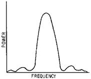
Transmitter energy is distributed symmetrically over a band of frequencies known
as the SPECTRUM.
A SPECTRUM Curve for a transmitter in good condition is shown
in the illustration.
4-24
The SPECTRUM ANALYZER and the ECHO BOX are
two instruments used to check transmitter performance.
One of the more important measurements that can be performed with the echo box
is RING TIME. Ring time gives a relative indication of both transmitter output power
and receiver sensitivity.
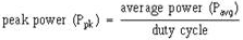
Transmitter Output Power MEASUREMENTS are a good indication
of overall transmitter operation. Power MEASUREMENTS are usually of average power
read in dBm. The average power dBm reading must be converted to watts and the peak
power calculated. The formula for peak power is:
RECEIVER Performance CHECKS determine receiver sensitivity,
TR recovery time, and receiver bandwidth.
You usually measure receiver sensitivity by measuring the MINIMUM DIsCERNIBLE
Signal (MDS) using the pulse method.
TR RECOVery time is the time required for the TR tube to DEIONIZE
after each transmitted pulse. You should keep a graph of TR recovery time to determine
when the TR tube should be replaced. If not replaced in a timely manner, a weak
TR tube will allow damage to the radar receiver.
Few radars can function without SUPPORT Systems. These support systems include
ELECTRICAL Power, DRY-AIR, and LIQUID-COOLING Systems.
The radar technician should learn the source and distribution routes for NORMAL
and Emergency Power for the radar.
The DRY AIR needed for electronic equipment can be supplied
by the ship's electronics dry-air system through an air control panel or from local
dehydrators.
Radar transmitters generate large amounts of heat. Most of this heat is dissipated
by a combination of AIR CONDITIONING, CABINET AIR BLowERS, and a DIsTILLED-WATER
COOLING system.
4-25
Personnel working on radars should always be aware of the hazards of RF Radiation
and X-RAY EMIsSION.
All posted Safety PRECautionS should be strictly observed.
Answers to Questions Q1. Through Q21.
A1. Frequency distribution.
A2. In the center.
A3. Symmetrical above and below the carrier frequency.
A4. Power and frequency.
A5. Average power, pulse width, and PRT.
A6. 1 milliwatt.
A7. Transmitter power loss.
A8. Minimum discernible signal (MDS).
A9. Attenuations of the directional coupler and the connecting cable.
A10. Half-power points.
A11. Recovery time.
A12. Three.
A13. Automatically.
A14. Manual bus transfer (MBT) unit.
A15. Work backwards from the load to the source.
A16. Ship's central dry-air system.
A17. Degree of dehydration.
A18. Pressure.
A19. Air conditioning.
A20. Primary and secondary.
A21. The primary loop.
4-26
| - |
Matter, Energy,
and Direct Current |
| - |
Alternating Current and Transformers |
| - |
Circuit Protection, Control, and Measurement |
| - |
Electrical Conductors, Wiring Techniques,
and Schematic Reading |
| - |
Generators and Motors |
| - |
Electronic Emission, Tubes, and Power Supplies |
| - |
Solid-State Devices and Power Supplies |
| - |
Amplifiers |
| - |
Wave-Generation and Wave-Shaping Circuits |
| - |
Wave Propagation, Transmission Lines, and
Antennas |
| - |
Microwave Principles |
| - |
Modulation Principles |
| - |
Introduction to Number Systems and Logic Circuits |
| - |
- Introduction to Microelectronics |
| - |
Principles of Synchros, Servos, and Gyros |
| - |
Introduction to Test Equipment |
| - |
Radio-Frequency Communications Principles |
| - |
Radar Principles |
| - |
The Technician's Handbook, Master Glossary |
| - |
Test Methods and Practices |
| - |
Introduction to Digital Computers |
| - |
Magnetic Recording |
| - |
Introduction to Fiber Optics |
| Note: Navy Electricity and Electronics Training
Series (NEETS) content is U.S. Navy property in the public domain. |
|