Module 10 - Introduction to Wave Propagation, Transmission Lines, and Antennas
Pages i,
1-1,
1-11,
1-21,
1-31,
1-41,
2-1,
2-11,
2-21,
2-31,
2-40,
3-1,
3-11,
3-21,
3-31,
3-41,
3-51,
4-1,
4-11,
4-21,
4-31,
4-41,
4-51, Index

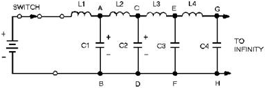
Figure 3-20. - Dc applied to an equivalent transmission line. As the switch is closed, the battery voltage is applied to the input terminals of the line. Now, C1 has
no charge and appears, effectively, as a short circuit across points a and B. The full battery voltage appears
across inductor L1. Inductor L1 opposes the change of current (0 now) and limits the rate of charge of C1.
Capacitor C2 cannot begin to charge until after C1 has charged. No current can flow beyond points a and B until C1
has acquired some charge. As the voltage across C1 increases, current through L2 and C2 charges C2. This action
continues down the line and charges each capacitor, in turn, to the battery voltage. Thus a voltage wave is
traveling along the line. Beyond the wavefront, the line is uncharged. Since the line is infinitely long, there
will always be more capacitors to be charged, and current will not stop flowing. Thus current will flow
indefinitely in the line.
Notice that current flows to charge the capacitors along the line. The flow of current is not advanced along the
line until a voltage is developed across each preceding capacitor. In this manner voltage and current move down
the line together in phase. Ac Applied to an Infinite Line An RF line displays
similar characteristics when an ac voltage is applied to its sending end or input terminals. In figure 3-21, view
A, an ac voltage is applied to the line represented by the circuit shown.
3-21

Figure 3-21. - Ac applied to an equivalent transmission line. In view B the generator voltage starts from zero (T1) and produces the voltage shown. As soon as a small
voltage change is produced, it starts its journey down the line while the generator continues to produce new
voltages along a sine curve. At T2 the generator voltage is 70 volts. The voltages still move along the line
until, at T3, the first small change arrives at point W, and the voltage at that point starts increasing. At T5,
the same voltage arrives at point X on the line. Finally, at T7, the first small change arrives at the receiving
end of the line. Meanwhile, all the changes in the sine wave produced by the generator pass each point in turn.
The amount of time required for the changes to travel the length of the line is the same as that required for a dc
voltage to travel the same distance. At T7, the voltage at the various points on the line is as follows:
At the generator:..................
-100 V
At point W:....................................
0 V
At point X:....................................
+100 V
At point Y:....................................
0 V If these voltages are plotted along the length of the line, the resulting curve is like the one shown in
figure 3-22, view A. Note that such a curve of instantaneous voltages resembles a sine wave. The changes in
voltage that occur between T7 and T8 are as follows:
3-22


Figure 3-22. - Instantaneous voltages along a transmission line. A plot of these new voltages produces the solid curve shown in figure 3-22, view B. For reference, the
curve from T7 is drawn as a dotted line. The solid curve has exactly the same shape as the dotted curve, but has
moved to the right by the distance X. Another plot at T9 would show a new curve similar to the one at T8, but
moved to the right by the distance Y. By analyzing the points along the graph just discussed, you should
be able to see that the actions associated with voltage changes along an RF line are as follows: 1. All
instantaneous voltages of the sine wave produced by the generator travel down the line in the order they are
produced.
2. At any point, a sine wave can be obtained if all the instantaneous voltages passing the point are plotted.
An oscilloscope can be used to plot these values of instantaneous voltages against time.
3-23
3. The instantaneous voltages (oscilloscope displays) are the same in all cases except that a phase
difference exists in the displays seen at different points along the line. The phase changes continually with
respect to the generator until the change is 360 degrees over a certain length of line. 4. All parts of
a sine wave pass every point along the line. a plot of the readings of an ac meter (which reads the effective
value of the voltage over a given time) taken at different points along the line shows that the voltage is
constant at all points. This is shown in view C of figure 3-22. 5. Since the line is terminated with a
resistance equal to Z 0, the energy arriving at the end of the line is absorbed by the resistance.
VELOCITY of WAVE PROPAGATION If a voltage is initially applied to the sending end of a
line, that same voltage will appear later some distance from the sending end. This is true regardless of any
change in voltage, whether the change is a jump from zero to some value or a drop from some value to zero. The
voltage change will be conducted down the line at a constant rate. Recall that the inductance of a line
delays the charging of the line capacitance. The velocity of propagation is therefore related to the values of L
and C. If the inductance and capacitance of the RF line are known, the time required for any waveform to travel
the length of the line can be determined. To see how this works, observe the following relationship:
Q = IT This formula shows that the total charge or quantity is equal to the current multiplied by the time the
current flows. Also:
Q = CE This formula shows that the total charge on a capacitor is equal to the capacitance multiplied by the
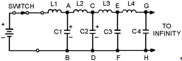
voltage across the capacitor. If the switch in figure 3-23 is closed for a given time, the quantity (Q) of
electricity leaving the battery can be computed by using the equation Q = IT. The electricity leaves the battery
and goes into the line, where a charge is built up on the capacitors. The amount of this charge is computed by
using the equation Q = CE.
3-24

Figure 3-23. - Dc applied to an equivalent transmission line. Since none of the charge is lost, the total charge leaving the battery during T is equal to the total
charge on the line. Therefore:
Q = IT = CE As each capacitor accumulates a charge equal to CE, the voltage across each inductor must change. As C1
in figure 3-23 charges to a voltage of E, point a rises to a potential of E volts while point B is still at zero
volts. This makes E appear across L2. As C2 charges, point B rises to a potential of E volts as did point A. At
this time, point B is at E volts and point C rises. Thus, we have a continuing action of voltage moving down the
infinite line. In an inductor, these circuit components are related, as shown in the formula

This shows that the voltage across the inductor is directly proportional to inductance and the change in
current, but inversely proportional to a change in time. Since current and time start from zero, the change in
time (DT) and the change in current (DI) are equal to the final time (T) and final current (I). For this case the
equation becomes:
ET = LI If voltage E is applied for time (T) across the inductor (L), the final current (I) will flow. The
following equations show how the three terms (T, L, and C) are related:
IT = CE
ET = LI For convenience, you can find T in terms of L and C in the following manner. Multiply the left and right
member of each equation as follows:
3-25
(IT)(ET) = (CE)(LI)
Then: EIT2 = LCEI
Dividing by (EI): T2 = LC
and
 This final equation is used for finding the time required for a voltage change to travel a unit length,
since L and C are given in terms of unit length. The velocity of the waves may be found by:

Where: D is the physical length of a unit This is the rate at which the wave travels over a unit
length. The units of L and C are henrys and farads, respectively. T is in seconds per unit length and V is in unit
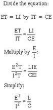
lengths per second. Determining Characteristic Impedance As previously discussed,
an infinite transmission line exhibits a definite input impedance. This impedance is the Characteristic Impedance
and is independent of line length. The exact value of this impedance is the ratio of the input voltage to the
input current. If the line is infinite or is terminated in a resistance equal to the characteristic impedance,
voltage and current waves traveling the line are in phase. To determine the characteristic impedance or
voltage-to-current ratio, use the following procedure:

3-26
Take the square root:

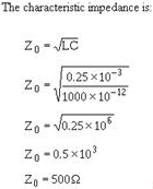
Example: A problem using this equation will illustrate how to determine the characteristics of a
transmission line. Assume that the line shown in figure 3-23 is 1000 feet long. a 100-foot (approximately 30.5
meter) section is measured to determine L and C. The section is found to have an inductance of 0.25 millihenries
and a capacitance of 1000 picofarads. Find the characteristic impedance of the line and the velocity of the wave
on the line.

If any other unit length had been considered, the values of L and C would be different, but their ratio
would remain the same as would the characteristic impedance.

3-27

REFLECTIONS ON a Transmission LINE Transmission line characteristics are based on an infinite line. a line cannot always be terminated in
its characteristic impedance since it is sometimes operated as an OPEN-ENDED line and other times as a
Short-Circuit at the receiving end. If the line is open-ended, it has a terminating impedance that is infinitely
large. If a line is not terminated in characteristic impedance, it is said to be finite. When a line is
not terminated in Z0, the incident energy is not absorbed but is returned along the only path available - the
transmission line. Thus, the behavior of a finite line may be quite different from that of the infinite line.
REFLECTION of DC Voltage FROM an OPEN Circuit The equivalent circuit of an open-ended
transmission line is shown in figure 3-24, view A. Again, losses are to be considered as negligible, and L is
lumped in one branch. Assume that (1) the battery in this circuit has an internal impedance equal to the
characteristic impedance of the transmission line (Zi = Z0); (2) the capacitors in the line are not charged before
the battery is connected; and (3) since the line is open-ended, the terminating impedance is infinitely large.
3-28

Figure 3-24. - Reflection from an open-ended line. When the battery is connected to the sending end as shown, a negative voltage moves down the line. This
voltage charges each capacitor, in turn, through the preceding inductor. Since Zi equals Z0,
one-half the applied voltage will appear across the internal battery impedance, Zi, and one-half across
the impedance of the line, Z0. Each capacitor is then charged to E/2 (view B). When the last capacitor
in the line is charged, there is no voltage across the last inductor and current flow through the last inductor
stops. With no current flow to maintain it, the magnetic field in the last inductor collapses and forces current
to continue to flow in the same direction into the last capacitor. Because the direction of current has not
changed, the capacitor charges in the same direction, thereby increasing the charge in the capacitor. Since the
energy in the magnetic field equals the energy in the capacitor, the energy transfer to the capacitor doubles the
voltage across the capacitor. The last capacitor is now charged to E volts and the current in the last inductor
drops to zero. At this point, the same process takes place with the next to the last inductor and
capacitor. When the magnetic field about the inductor collapses, current continues to flow into the next to the
last capacitor, charging it to E volts. This action continues backward down the line until the first capacitor has
been fully charged to the applied voltage. This change of voltage, moving backward down the line, can be thought
of in the following manner. The voltage, arriving at the end of the line, finds no place to go and returns to the
sending end with the same polarity (view C). Such action is called REFLECTION. When a reflection of
voltage occurs on an open-ended line, the polarity is unchanged. The voltage change moves back to the source,
charging each capacitor in turn until the first capacitor is charged to the
3-29
source voltage and the action stops (view D). As each capacitor is charged, current in each inductor
drops to zero, effectively reflecting the current with the opposite polarity (view C). Reflected current of
opposite polarity cancels the original current at each point, and the current drops to zero at that point. When
the last capacitor is charged, the current from the source stops flowing (view D). Important facts to
remember in the reflection of dc voltages in open-ended lines are:
· Voltage is reflected from an open
end without change in polarity, amplitude, or shape.
· Current is reflected from an open end with
opposite polarity and without change in amplitude or shape. REFLECTION of DC Voltage FROM a Short
Circuit
a Short-CircuitED line affects voltage change differently from the way an open-circuited line affects it. The
voltage across a perfect short circuit must be zero; therefore, no power can be absorbed in the short, and the
energy is reflected toward the generator. The initial circuit is shown in figure 3-25, view A. The initial
voltage and current waves (view B) are the same as those given for an infinite line. In a short-circuited line the
voltage change arrives at the last inductor in the same manner as the waves on an open-ended line. In this case,
however, there is no capacitor to charge. The current through the final inductor produces a voltage with the
polarity shown in view C. When the field collapses, the inductor acts as a battery and forces current through the
capacitor in the opposite direction, causing it to discharge (view D). Since the amount of energy stored in the
magnetic field is the same as that in the capacitor, the capacitor discharges to zero.
3-30
| - |
Matter, Energy,
and Direct Current |
| - |
Alternating Current and Transformers |
| - |
Circuit Protection, Control, and Measurement |
| - |
Electrical Conductors, Wiring Techniques,
and Schematic Reading |
| - |
Generators and Motors |
| - |
Electronic Emission, Tubes, and Power Supplies |
| - |
Solid-State Devices and Power Supplies |
| - |
Amplifiers |
| - |
Wave-Generation and Wave-Shaping Circuits |
| - |
Wave Propagation, Transmission Lines, and
Antennas |
| - |
Microwave Principles |
| - |
Modulation Principles |
| - |
Introduction to Number Systems and Logic Circuits |
| - |
- Introduction to Microelectronics |
| - |
Principles of Synchros, Servos, and Gyros |
| - |
Introduction to Test Equipment |
| - |
Radio-Frequency Communications Principles |
| - |
Radar Principles |
| - |
The Technician's Handbook, Master Glossary |
| - |
Test Methods and Practices |
| - |
Introduction to Digital Computers |
| - |
Magnetic Recording |
| - |
Introduction to Fiber Optics |
| Note: Navy Electricity and Electronics Training
Series (NEETS) content is U.S. Navy property in the public domain. |
|


