|
||||||||||||||||||||||||||||||||||||||||||||||||||||||||||||||||||||||||||||||||||||||||||||||||
 |
||||||||||||||||||||||||||||||||||||||||||||||||||||||||||||||||||||||||||||||||||||||||||||||||
A History of Fixed-Value Resistor Electronic Components© |
||||||||||||||||||||||||||||||||||||||||||||||||||||||||||||||||||||||||||||||||||||||||||||||||
|
A Structured Historical and Technical Report 1. Executive Summary Fixed-value resistors are among the simplest-looking components in electronics, but their development reflects nearly the entire history of electrical science, telecommunications, electric lighting, industrial power, radio, military electronics, printed circuits, hybrid microelectronics, and surface-mount manufacturing. The resistor's conceptual foundation began before there were electronic components in the modern sense. It emerged from nineteenth-century studies of electrical conduction, especially Georg Simon Ohm's 1827 formulation of the relationship among voltage, current, and resistance in Die galvanische Kette, mathematisch bearbeitet. Once telegraphy, electrical standards laboratories, and power engineering required repeatable amounts of resistance, physical resistance elements evolved from laboratory wire coils and resistance boxes into industrial wirewound units, carbon composition radio resistors, deposited film resistors, precision metal-film and foil resistors, thick-film chip resistors, and specialized high-voltage, high-power, current-sense, fusible, pulse, and microwave resistors. In the earliest period, roughly 1820 to 1880, resistors were not yet discrete commodity components. They were resistance coils, resistance boxes, bridges, rheostats, telegraph line simulators, galvanometer shunts, and standards of resistance. The crucial developments were scientific and metrological: Ohm's law, Wheatstone's bridge method, described in 1843 in the Philosophical Transactions of the Royal Society, and the creation of reproducible electrical units such as the ohm. Materials were mostly metals: copper for conductors, German silver or nickel silver for resistance coils, platinum and platinum-silver for stable standards, and later manganin and constantan for precision resistors because of their relatively low temperature coefficients. Electronics & High Technology Components
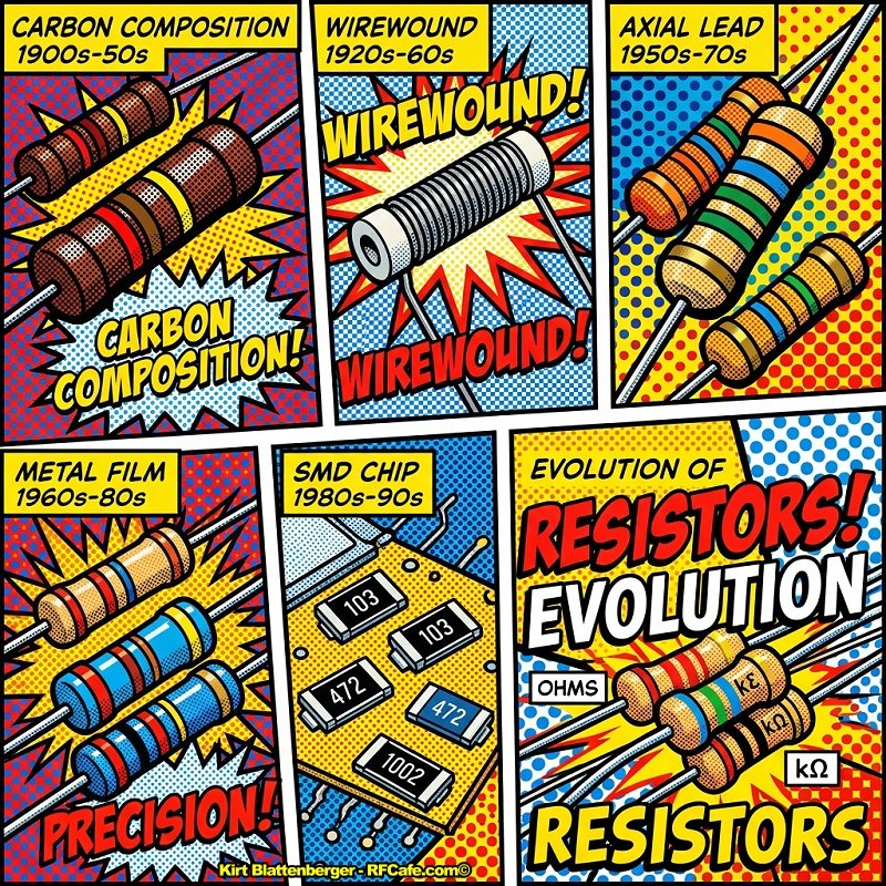
The second phase, approximately 1880 to 1920, was driven by electric lighting, traction, industrial motor control, telephony, telegraphy, and the rapid expansion of measurement instrumentation. Wirewound resistors and resistor banks became major industrial products. Resistance alloys became critical. Edward Weston's copper-manganese-nickel resistance alloys and Albert L. Marsh's nichrome alloy were especially important. Marsh's nickel-chromium alloy patent, assigned to Hoskins Manufacturing, is a landmark in heater and resistor materials: US811859A, 1906. These alloys allowed higher operating temperatures, more stable resistance, and more compact power resistors than earlier iron, German silver, or carbon elements. The third phase, roughly 1920 to 1960, was the age of radio and mass electronics. Vacuum-tube receivers, transmitters, test equipment, radar, and later television required large numbers of small, inexpensive fixed resistors. Carbon composition resistors, made from carbon or graphite powder mixed with insulating filler and binder, molded around leads, and color coded, became the dominant low-cost resistor type. They were compact, noninductive, inexpensive, and tolerant of short energy pulses, but they were noisy, moisture sensitive, drifted with age and heat, and had relatively poor tolerance and temperature coefficient compared with wirewound or later film resistors. Companies such as Allen-Bradley, International Resistance Company, Stackpole, Erie Resistor, Ohmite, Sprague, Centralab, and others supplied resistors to the radio and military electronics industries. Some corporate origin stories are well documented. For example, Ohmite identifies its founding in Chicago in 1925. Exact firsts for carbon composition fixed resistors are harder to prove because many early product introductions were recorded in catalogs and trade literature rather than in peer-reviewed technical papers. The fourth phase, roughly 1950 to 1980, saw film resistors overtake carbon composition in many applications. Carbon film resistors, formed by depositing carbon on ceramic rods and trimming the film to value, offered lower noise and better stability than carbon composition at modest cost. Metal film, metal oxide film, and precision wirewound resistors served applications requiring improved tolerance, temperature coefficient, voltage handling, surge resistance, or temperature capability. The same era produced hybrid microelectronics, in which resistive films were printed or deposited on ceramic substrates. Thick-film resistor technology, often based on ruthenium-oxide or related conductive particles in glassy binders screen-printed and fired on alumina, became foundational for resistor networks and later surface-mount chip resistors. The fifth phase, from roughly 1980 to the present, is dominated by surface-mount chip resistors and specialized resistor technologies. Thick-film chip resistors became the commodity standard because they are small, cheap, compatible with automated assembly, and available in enormous volumes. Thin-film chip resistors provide better precision, stability, and noise. Bulk metal foil resistors, associated especially with Felix Zandman and Vishay Intertechnology, provide extremely low temperature coefficients and exceptional long-term stability. Vishay's corporate history traces its founding to 1962 and the commercialization of foil resistor technology. The essential historical pattern is clear: each new resistor technology solved a limitation of the previous generation. Wirewound resistors offered power and precision but were bulky and inductive. Carbon composition offered low cost and compactness but poor stability and noise. Carbon film improved stability and cost balance. Metal film improved tolerance and noise. Metal oxide improved high-temperature and overload behavior. Thick film enabled inexpensive surface-mount production. Thin film and foil enabled precision. Metal strip and shunt resistors enabled high-current sensing. Modern high-voltage, high-frequency, pulse, fusible, and power resistors are highly specialized descendants of these earlier material and manufacturing choices. 2. Key Findings
3. Detailed Analysis 3.1 What Is Meant by a Fixed-Value Resistor? A fixed-value resistor is an electrical component designed to provide an approximately constant resistance value under specified conditions. It differs from a variable resistor, rheostat, or potentiometer because its resistance is not intended to be adjusted during normal use. In practice, fixed has always meant fixed within tolerance and operating limits. Resistance varies with temperature, voltage stress, frequency, humidity, age, mechanical strain, and power dissipation. The basic design requirements have remained remarkably constant:
A perfect resistor obeys Ohm's law exactly. Real resistors do not. Their history is largely the story of making resistance more reproducible, compact, stable, inexpensive, and manufacturable. 3.2 Scientific Foundations Before the Component Industry Ohm and the Mathematical Concept of Resistance Georg Simon Ohm, working in Germany, published Die galvanische Kette, mathematisch bearbeitet in 1827. In that work he formulated the relationship now called Ohm's law: current is proportional to electromotive force and inversely proportional to resistance. Ohm's ideas were not immediately accepted everywhere, but they became central to electrical science. Before Ohm, experimenters had observed that different conductors opposed current differently, but there was not yet a mature mathematical framework for treating resistance as an electrical quantity. Ohm's work allowed resistance to be treated quantitatively. That made it possible to design circuits rather than merely observe them. Wheatstone Bridge and Precision Comparison Charles Wheatstone's 1843 paper on measuring electrical resistance gave practical prominence to bridge methods, although the bridge circuit itself had earlier roots in work by Samuel Hunter Christie. Wheatstone's work was influential enough that the circuit became known as the Wheatstone bridge. See Wheatstone's 1843 Royal Society paper. The bridge was crucial because it allowed unknown resistances to be compared accurately against known resistances. This matters for resistor history because the first high-quality resistors were often not circuit components in radios or amplifiers. They were standards and comparison elements in measurement apparatus. Precision resistance was first a metrology problem. The ohm and Electrical Standardization The growth of telegraphy made resistance a practical commercial concern. Telegraph lines could be hundreds of miles long, and their resistance affected signal strength, relay operation, and fault diagnosis. Engineers needed common units. The British Association for the Advancement of Science formed committees in the nineteenth century to define electrical standards. The ohm eventually became the named unit of electrical resistance, later incorporated into international systems of units. Modern SI treats the ohm as the derived unit volt per ampere. See NIST SI electrical units. Early resistance standards were often physical artifacts: coils of wire or columns of mercury. Mercury was attractive for standards because a defined column of mercury at a specified temperature could, in principle, reproduce a resistance. But for practical instruments and components, mercury was inconvenient. Coiled wire remained the everyday solution. 3.3 Early Resistance Materials: Metals, Alloys, and Carbon Copper Copper was widely available and highly conductive. That made it useful for wiring but usually undesirable for compact resistors. A copper resistor of useful value required long length or fine wire, and copper's temperature coefficient is relatively high, about plus 3900 ppm per °C near room temperature. Copper therefore appeared in early resistance apparatus mainly as connecting wire, not as the preferred resistance material. Iron and Steel Iron wire was sometimes used in early electrical work and in power resistor grids. It had higher resistivity than copper and was mechanically strong. But iron oxidizes, changes resistance significantly with temperature, and can have magnetic effects. It was adequate for rugged industrial use but not ideal for precision. German Silver or Nickel Silver German silver, also called nickel silver, is a copper-nickel-zinc alloy containing no actual silver. It was important in nineteenth-century resistance coils because it had much higher resistivity than copper and a lower temperature coefficient than pure copper. Resistance boxes used in laboratories and telegraph offices often relied on coils of German silver or similar alloys wound on bobbins or cards, with switching plugs selecting values. Platinum and Platinum Alloys Platinum was valued for chemical stability and high melting point. Platinum and platinum-silver alloys were used in some early standards and precision apparatus. The disadvantages were cost and, depending on alloy, temperature coefficient. Platinum was too expensive for ordinary resistors but important in metrology and high-temperature applications. Carbon Carbon has a long history in electrical technology: arc lamps, carbon microphones, battery electrodes, lamp filaments, and contacts. It has relatively high resistivity compared with metals and can withstand high temperatures in suitable environments, but its properties depend strongly on form: graphite, carbon black, amorphous carbon, compressed powder, deposited carbon film, or composite mixture. Carbon's eventual success in fixed resistors came from its compatibility with molding and mass production. 3.4 Resistance Coils, Boxes, Shunts, and Rheostats In the nineteenth century, the practical uses of resistance included telegraph line testing, galvanometer calibration, battery current control, bridge measurements, laboratory experiments, arc-lamp regulation, motor starting and speed control, dummy loads, load banks, instrument multipliers, and shunts. A resistance box might contain many fixed coils selected by plugs or switches. Each coil was a fixed resistor, although the box as a whole functioned as an adjustable instrument. Coils were wound noninductively when needed, often by folding wire back on itself or using bifilar winding. Noninductive winding became important whenever resistance had to remain resistive rather than inductive under changing current. Power Limitations of Early Wire Resistors For wire resistors, the maximum current was determined by heating: P = I2R The resistor had to dissipate that heat without melting, oxidizing, charring insulation, or changing value excessively. Early coils used silk, cotton, shellac, mica, ceramic, slate, or air spacing. Organic insulation limited temperature severely. High-power resistance grids used open air, porcelain, ceramic, or metal frames. Voltage Limitations Voltage rating depended on distance between turns, insulation between wire and support, surface creepage, air breakdown, switch spacing, contamination, and humidity. High-voltage resistors required long physical structures because electric field stress had to be distributed. 3.5 The Rise of Industrial Power Resistors By the late nineteenth century, electrical systems moved from laboratories to factories, streetcars, mines, elevators, and lighting plants. Motors needed starting resistors because a stationary DC motor has low armature back EMF and can draw excessive current. Streetcars and cranes used resistor banks for acceleration control. Load banks and braking resistors converted electrical energy into heat. Industrial resistors were often not cylindrical components. They were cast iron grids, steel grids, edge-wound metal strip, porcelain-mounted wire coils, mica-card resistors, open-coil resistor frames, and oil-immersed resistor banks. These designs handled far more power than small electronic resistors, from hundreds of watts to many kilowatts, but were physically large. They were limited by temperature rise, oxidation, mechanical stress, enclosure ventilation, and safety. 3.6 The Critical Role of Resistance Alloys A good resistance alloy needs high resistivity, low temperature coefficient, oxidation resistance, ductility, low thermoelectric EMF against copper, long-term stability after heat treatment, manufacturability, and reasonable cost. No single alloy is best for all purposes. Precision standards, heating elements, current shunts, and power resistors require different compromises. Constantan Constantan is a copper-nickel alloy, typically around 55% copper and 45% nickel. It has relatively high resistivity and a low temperature coefficient compared with copper. It is also used in thermocouples because of its thermoelectric properties. For resistors, constantan was useful in instrument shunts, rheostats, and general resistance wire. The exact invention history is somewhat tangled because copper-nickel resistance alloys developed through multiple metallurgical investigations in the nineteenth century. Manganin Manganin is a copper-manganese-nickel alloy, often nominally about 84% copper, 12% manganese, and 4% nickel, though compositions vary. It became one of the most important precision resistance alloys because it has low temperature coefficient near room temperature after proper treatment, good long-term stability, relatively low thermal EMF against copper, and adequate resistivity for precision coils and shunts. Edward Weston patented resistance alloys in the late nineteenth century. One relevant patent is US400481A, issued in 1889. Nichrome Nichrome, a nickel-chromium resistance alloy, was a major breakthrough for high-temperature resistance elements. Albert L. Marsh, working with Hoskins Manufacturing in the United States, developed nickel-chromium alloys suitable for resistance heating. His patent US811859A was issued in 1906. Nichrome's importance lies in its oxidation resistance and ability to operate at red heat. It made compact electric heaters possible, but it also transformed power resistor design. Typical uses included wirewound power resistors, rheostats, heating elements, load banks, ceramic-core resistors, braking resistors, and appliance and industrial heaters. Kanthal and Iron-Chromium-Aluminum Alloys Iron-chromium-aluminum alloys, commonly associated with the Kanthal name, offered even higher operating temperature and good oxidation resistance due to alumina scale formation. Kanthal traces its origin to Hans von Kantzow in Sweden in the 1930s. These alloys became important in heating elements and high-temperature resistors, though nichrome remained widely used. Later Precision Alloys Twentieth-century precision resistors used proprietary alloys designed for low TCR, low thermal EMF, and stability. Evanohm and Karma-type nickel-chromium-based alloys are examples. These were especially important in precision wirewound resistors, shunts, and instrumentation. 3.7 Early Fixed Resistors in Radio and Electronics The development of vacuum-tube electronics changed resistor history. Early radio receivers, audio amplifiers, oscillators, and transmitters required grid leak resistors, plate load resistors, cathode bias resistors, voltage dividers, screen-grid dropping resistors, meter multipliers, bleeder resistors, filter discharge resistors, and detector load resistors. One of the earliest common fixed resistors in radio was the grid leak resistor. In regenerative and detector circuits, a high-value resistor allowed accumulated grid charge to leak away. Early grid leaks might be made from pencil marks, carbonized materials, or sealed cartridge-like components. Values were often in the megohm range. These early high-value resistors were difficult to make stable because humidity, contamination, and surface leakage mattered. Wirewound resistors served where precision or power was needed. In tube equipment they appeared as power-supply bleeders, voltage dividers, cathode resistors, meter multipliers, transmitter dummy loads, audio attenuators, and laboratory standards. Their limitations were size, cost, and parasitic inductance. 3.8 Carbon Composition Resistors A carbon composition resistor consists of a resistive body made from a mixture of carbon or graphite powder, insulating filler, and binder. Metal leads are embedded or attached, and the body is molded and cured. The resistance value is controlled by the carbon-to-insulator ratio, geometry, pressure, and processing. Common binders historically included phenolic resins and other organic systems. Fillers could include ceramic or clay-like materials. The external body was often molded into a cylindrical shape and painted or coated. Color bands indicated value and tolerance. Why Carbon Composition Succeeded
Major Manufacturers
Because many early introductions were documented in catalogs and trade magazines, definitive claims such as the first carbon composition fixed resistor should be treated cautiously unless tied to a specific patent, catalog date, or archival source. Electrical Characteristics Typical carbon composition characteristics varied by manufacturer and period, but historically common values included tolerances of plus or minus 20%, 10%, and later 5%; power ratings of 1/8 W, 1/4 W, 1/2 W, 1 W, 2 W, and larger; maximum working voltage often in the range of a few hundred volts for small parts; high temperature coefficient; high excess noise; significant voltage coefficient in high-value resistors; and long-term drift worsened by heat and humidity. The maximum current follows: I At high resistance values, voltage rating rather than power rating often dominates: V For example, a 1/2 W, 1 MΩ resistor would have a theoretical power-limited voltage of about 707 V, but a real part might be rated only 350 V or 500 V. Failure Modes
Vintage radio restorers often find carbon composition resistors that have drifted high by 20%, 50%, or more. This reflects the material system's susceptibility to moisture and thermal history. Pulse Behavior One reason carbon composition resistors survived in niche use is pulse capability. Because the resistive path occupies a bulk volume rather than a thin film, short energy pulses can be distributed through more material. For surge suppression, snubbers, ignition circuits, and certain RF applications, carbon composition resistors remained useful even after film resistors became common. Modern pulse-rated thick-film, wirewound, and composition alternatives have largely replaced them. 3.9 Resistor Color Coding and Standardization As resistors became small and mass-produced, printing values directly on them was inconvenient. Color coding became the solution. The familiar resistor color code assigns digits to colors: black 0, brown 1, red 2, orange 3, yellow 4, green 5, blue 6, violet 7, gray 8, white 9, with multiplier and tolerance bands. The modern international standard for marking resistors and capacitors is IEC 60062. Earlier color-code systems were used by radio manufacturers and trade associations before international standardization. Preferred-number series such as E6, E12, E24, E48, E96, and E192 also became important. These series distribute values logarithmically so that tolerances overlap efficiently. 3.10 Wirewound Resistors as Electronic Components Wirewound resistors use resistance wire wound around an insulating core, usually ceramic, fiberglass, or molded material. The winding is terminated to leads or end caps and coated with enamel, cement, silicone, vitreous enamel, or ceramic. Major forms include precision wirewound resistors, power wirewound resistors, cement-encased resistors, vitreous enamel resistors, aluminum-housed chassis-mount resistors, noninductive wirewound resistors, current-sense shunts, resistor networks, and decade units.
For AC, pulse, and RF use, inductance is undesirable. Techniques include bifilar winding, Ayrton-Perry winding, flat strip geometries, and bulk resistive slabs for RF loads. Noninductive wirewounds are not perfectly noninductive, but they greatly improve high-frequency behavior compared with ordinary coils. Wirewound power resistors may be rated from fractions of a watt to hundreds of watts in a single component, and resistor banks can dissipate kilowatts or megawatts intermittently. Limits are set by element temperature, core temperature, coating temperature, ambient temperature, cooling method, dielectric strength, mounting surface, pulse energy, and thermal cycling. 3.11 Carbon Film Resistors Carbon film resistors are made by depositing a thin carbon layer on an insulating substrate, commonly ceramic. The film is trimmed, often by cutting a helical spiral, to obtain the desired resistance. End caps and leads are attached, and the resistor is coated. Carbon film technology became increasingly important after World War II and was common by the 1950s and 1960s. It provided a low-cost improvement over carbon composition. Advantages over Carbon Composition
Carbon film resistors still had higher noise than metal film, limited pulse energy compared with carbon composition, spiral-cut inductance and voltage stress, moderate temperature coefficient, and susceptibility to overload damage of the thin film. 3.12 Metal Film Resistors Metal film resistors are made by depositing a thin metallic resistive layer, often nickel-chromium or similar alloy, on a ceramic substrate. Deposition methods include vacuum evaporation, sputtering, or chemical processes. The film is trimmed to value and protected by coating. Metal film resistors became increasingly important in the mid-twentieth century as instrumentation, computers, military electronics, and communication equipment demanded better stability and lower noise than carbon resistors could provide. Modern metal film resistors commonly offer tolerance of plus or minus 1%, 0.5%, 0.1%, or better; TCR of 100 ppm per °C, 50 ppm per °C, 25 ppm per °C, or lower; low excess noise; good long-term stability; and moderate pulse capability. Their limitations are film damage under surges and finite working voltage. 3.13 Metal Oxide Film Resistors Metal oxide film resistors often use tin oxide or related oxide films deposited on ceramic rods. They are especially useful for higher temperature, flameproof, and overload-resistant applications. Compared with carbon film, metal oxide film resistors generally offer higher operating temperature, better overload behavior, flame-resistant construction, better stability under heat, and suitability for power and surge applications. They are usually not as precise or low-noise as high-grade metal film or foil resistors. 3.14 Cermet and Thick-Film Resistors Thick-film resistors are made by screen-printing a resistive paste onto a substrate, usually alumina ceramic, and firing it at high temperature. The paste contains conductive particles, glass frit, organic vehicle, and additives. After firing, a composite resistive film remains. Common conductive systems include ruthenium oxide and related compounds. Thick-film technology became prominent in hybrid microelectronics during the 1950s and 1960s, then became dominant in surface-mount chip resistors. Before monolithic integrated circuits could include all necessary passive components economically, hybrid circuits placed printed resistors, conductors, and mounted semiconductor chips on ceramic substrates. Thick-film resistors could be laser trimmed to precise values. Surface-Mount Chip Resistors The modern rectangular chip resistor is usually a thick-film resistor on alumina with metal terminations. Typical construction includes an alumina ceramic substrate, terminations, screen-printed resistive film, firing, laser trimming, protective glass or epoxy overcoat, nickel barrier and tin solderable termination, singulation, and tape-and-reel packaging. Common package sizes include 2512, 2010, 1206, 0805, 0603, 0402, 0201, 01005, and smaller. The numbers historically refer to approximate dimensions in hundredths of an inch, though metric designations also exist. Typical commodity thick-film chip resistor ratings vary by size and manufacturer, but approximate examples are:
These are representative values only. Actual designs require manufacturer datasheets.
3.15 Thin-Film Resistors Thin-film resistors use a very thin deposited resistive layer, often nickel-chromium, tantalum nitride, or similar material, on a ceramic or silicon substrate. Deposition is typically by sputtering or evaporation, followed by photolithography or laser trimming. Thin-film resistors offer tight tolerance, low TCR, low noise, good ratio matching in networks, better high-frequency behavior, and good long-term stability. They are widely used in precision analog circuits, resistor networks, instrumentation amplifiers, data converters, RF circuits, and high-reliability applications. Their main disadvantages are higher cost and lower surge energy capacity compared with some thick-film or wirewound types. 3.16 Bulk Metal Foil Resistors Bulk metal foil resistors are associated especially with Felix Zandman, who founded Vishay Intertechnology in 1962. Vishay's company history ties its origin to foil resistor technology. Zandman's work built on strain-gage and stress-analysis expertise, using bonded metal foil patterns on stable substrates to achieve extremely low temperature coefficient and high stability. A foil resistor uses a thin metal foil bonded to a substrate. The foil pattern is photoetched. The substrate and foil are selected so that changes in foil resistivity with temperature are compensated by mechanical strain effects from differential thermal expansion. This can produce very low TCR. High-grade foil resistors can achieve TCR below 1 ppm per °C in selected ranges, tolerances down to 0.005% or better, excellent load-life stability, low noise, low thermal EMF designs, and excellent ratio stability in networks. They are used in metrology, precision instrumentation, aerospace, medical equipment, audio measurement, data acquisition, and calibration equipment. They are expensive and specialized. 3.17 Resistor Networks and Arrays As circuits became more complex, manufacturers combined multiple resistors in one package. Early examples included voltage dividers and precision decade networks. Later forms included SIP resistor packs, DIP resistor networks, thick-film hybrid networks, thin-film matched networks, integrated resistor arrays, and surface-mount resistor arrays. Networks are important because matching can matter more than absolute value. In a differential amplifier or DAC ladder, two resistors that track each other over temperature are more valuable than two individually precise but mismatched parts. Thin-film networks excel here. 3.18 Current-Sense and Shunt Resistors Current measurement required low-value resistors from the beginning of electrical instrumentation. A shunt resistor carries most of the current while a meter measures the small voltage drop across it. Early shunts used manganin or similar alloys because low TCR and low thermal EMF were important. Four-terminal Kelvin connections were adopted to separate current-carrying terminals from voltage-sensing terminals. Modern current-sense resistors include metal strip resistors, manganin shunts, electron-beam welded composite shunts, foil sense resistors, thick-film low-ohm chips, and four-terminal SMD current sensors. They are used in switch-mode power supplies, battery management, motor drives, automotive electronics, RF power control, and instrumentation. At very low resistance values, parasitic resistance and inductance dominate. For example: P = I2R = 502 x 0.001 = 2.5 W That is a 1 mΩ resistor carrying 50 A. The voltage signal is only 50 mV. Solder joints, copper traces, thermoelectric voltages, and thermal gradients become design-critical. 3.19 High-Voltage Resistors High-voltage resistors are used in CRT supplies, X-ray equipment, photomultiplier dividers, electrostatic equipment, high-voltage probes, capacitor discharge circuits, pulse modulators, power transmission measurement, radar, and microwave systems. High-voltage resistors are limited by electric field gradient along the resistive element, surface creepage, coating dielectric strength, corona discharge, partial discharge, voltage coefficient, ambient humidity, contamination, and energy absorption during transients. Long resistors are often used to spread voltage. Spiral cuts can create local high field gradients, so high-voltage resistors may use special geometries. Television receivers, oscilloscopes, radar sets, and photomultiplier instruments all required compact high-value, high-voltage resistors. This pushed development of stable film resistors and molded high-voltage resistor assemblies. 3.20 High-Frequency and RF Resistors At radio frequencies, a resistor's parasitic inductance and capacitance matter. A wirewound resistor may behave like an inductor. A spiral-trimmed film resistor may have distributed inductance and capacitance. Leads themselves are inductive. Carbon composition resistors were historically useful at RF because they were relatively noninductive. Amateur radio and military RF equipment often used them in grid stoppers, parasitic suppressors, and dummy loads. However, their stability and availability declined. Modern RF resistors include thin-film chip resistors, flange-mounted terminations, thick-film attenuator resistors, beryllia, aluminum nitride, or alumina substrates, 50-ohm microwave loads, and high-power RF terminations. Their design is electromagnetic as much as resistive. 3.21 Fusible, Flameproof, and Safety Resistors As consumer electronics grew, resistor failure behavior became a safety issue. A resistor in a power supply may overheat during faults. Ordinary carbon or film resistors could char, smoke, or ignite nearby materials. Fusible resistors are designed to open safely under overload. Flameproof resistors use coatings and materials that resist burning. Metal oxide film and specially designed wirewound parts are common in this role. Modern safety standards, including IEC and UL component requirements, shaped these designs. The resistor became not just an electrical component but a safety component. 3.22 Environmental and Military Influences World War II accelerated resistor development. Radar, communications, proximity fuzes, sonar, aircraft electronics, and fire-control systems required reliable components in harsh environments. Resistors had to survive vibration, humidity, temperature extremes, and mass production. Military specifications encouraged standardization of sizes, ratings, tolerances, marking, and testing. After the war, electronics entered aviation, computing, missiles, medical equipment, telecommunications, and industrial control. Reliability became a discipline. Resistors were tested for load life, temperature cycling, moisture resistance, solderability, shock and vibration, short-time overload, dielectric strength, and flame resistance. 3.23 The Integrated Circuit and the Changing Role of Discrete Resistors Integrated circuits contain resistors internally, but IC resistors have limitations in absolute value, tolerance, voltage, temperature coefficient, and power. Therefore, discrete fixed resistors remained essential. ICs changed discrete resistor demand in two opposite ways. They reduced the number of discrete biasing resistors in many circuits, but they created huge demand for precision external resistors, pullups, terminations, current-sense parts, feedback dividers, and surface-mount arrays. 3.24 Surface-Mount Technology and Miniaturization Surface-mount technology became dominant because it reduced size, improved assembly speed, and supported automated placement. Chip resistors were ideal SMT parts: rectangular, robust enough for pick-and-place, and easy to terminate. Miniaturization changed resistor limitations. In through-hole electronics, a 1/4 W resistor was physically large enough to tolerate abuse. In 0402 or 0201 packages, the thermal mass is tiny. Designers must consider board land pattern, copper area, ambient temperature, derating curves, solder joint fatigue, pulse energy, ESD, maximum element voltage, contamination, and leakage. 3.25 Voltage, Current, and Power Limitations Across Resistor History For any resistor: V = IR P = VI = I2R = V2/R These equations imply three different limits: current limit, voltage limit, and power or temperature limit. The safe operating area is the intersection of all three. Low-value resistors are usually current- and power-limited. For example, a 0.1 Ω resistor at 5 A dissipates 2.5 W. Voltage is only 0.5 V, but heating is substantial. High-value resistors are often voltage-limited. For example, a 10 MΩ, 1/4 W resistor would mathematically dissipate 1/4 W at 1581 V, but a small resistor may be rated for only 200 V or 500 V. Above that, film breakdown, surface leakage, arcing, or voltage coefficient may dominate. Most resistors are rated at a specified ambient temperature, often 70°C for general electronics parts. Above that, allowable power decreases. Pulse ratings cannot be inferred from continuous power rating alone. A resistor may survive 1 W continuously but fail from a 1 ms high-energy pulse if the element develops a local hot spot. 3.26 Materials Timeline
3.27 Major Manufacturers and Their Historical Roles
3.28 Resistor History by Application
3.29 Reliability Evolution Carbon composition reliability problems included humidity drift, poor tolerance, noise, and overload damage. Nevertheless, carbon composition resistors were acceptable in many consumer circuits because tubes and other components also had broad tolerances. Film resistors improved stability but introduced new failure modes: film cracking, spiral hot spots, overload opens, and coating defects. SMD resistors improved assembly but introduced board-level mechanical stress, solder-joint cracking, sulfur corrosion of silver terminations, and ESD or pulse vulnerability. Anti-sulfur chip resistors were developed for harsh environments. Modern resistor datasheets specify tests such as load life, damp heat, temperature cycling, short-time overload, resistance to solder heat, terminal strength, insulation resistance, dielectric withstand voltage, and flammability. 3.30 Environmental Regulations Late twentieth- and early twenty-first-century environmental regulations affected resistor construction. Lead-free soldering required terminations compatible with higher reflow temperatures and tin finishes. RoHS restrictions pushed changes in materials and plating. These changes sometimes introduced new reliability concerns, such as tin whiskers, though passive chip resistor terminations are typically engineered with barrier layers to reduce risk. 3.31 Comparison of Major Fixed Resistor Types
4. Open Questions and Debates in the Field Who Made the First Commercial Fixed Resistor? There is no simple answer. Fixed resistance elements existed in resistance boxes and telegraph equipment long before small radio resistors. Carbon grid leaks existed before standardized molded resistors. Wirewound power resistors existed before carbon composition radio resistors. Therefore, the answer depends on definition: first fixed resistance element, first cataloged fixed resistor, first molded carbon composition resistor, first axial lead resistor resembling the modern part, or first mass-produced radio resistor. Exact Dating of Carbon Composition Adoption (carbon dating? yuk, yuk) Carbon composition resistors became common in the 1920s and 1930s, but exact transition dates varied by country, manufacturer, and application. Early radios used wirewound, carbon grid leak, cartridge, and composition types side by side. Carbon Composition Versus Film in Pulse Applications Some engineers still prefer old-style carbon composition resistors for certain pulse or RF parasitic-suppression applications. Others argue that modern pulse-rated film, bulk ceramic, or noninductive wirewound resistors are superior and more reliable. The answer is application-specific. Long-Term Stability of Vintage Resistors Vintage restorers often debate whether to replace all old carbon composition resistors or only those out of tolerance. Historically accurate restoration may retain original parts, while reliability-oriented restoration replaces them. Since carbon composition parts can continue drifting, both positions have merit depending on the goal. Thin Film Versus Thick Film for Precision Designs Thin film generally has lower noise and better stability, but thick-film resistor networks can be laser-trimmed economically and may be adequate. Precision analog designers debate cost, voltage coefficient, moisture behavior, long-term drift, and ratio tracking. Reliability Effects of Miniaturization Very small chip resistors save space but have lower voltage, lower pulse energy, and greater susceptibility to board strain. The industry continues to debate optimal derating rules, especially in automotive and high-reliability electronics. Material Supply and Regulation Ruthenium-based thick-film systems, nickel, tin, silver, palladium, and specialty alloys have supply-chain and environmental implications. Future resistor materials may be influenced by cost, availability, and regulation as much as by electrical performance. 5. Sources Cited and Suggested Further Reading
Closing Note The history of the fixed resistor is best understood as several overlapping histories: scientific measurement, industrial power control, radio mass production, precision instrumentation, military reliability, and microelectronic manufacturing. The component's apparent simplicity hides two centuries of work in physics, metallurgy, ceramics, carbon chemistry, polymer science, printing, vacuum deposition, laser trimming, safety engineering, and automated assembly.
AI Technical Trustability Update While working on an update to my RF Cafe Espresso Engineering Workbook project to add a couple calculators about FM sidebands (available soon). The good news is that AI provided excellent VBA code to generate a set of Bessel function plots. The bad news is when I asked for a table showing at which modulation indices sidebands 0 (carrier) through 5 vanish, none of the agents got it right. Some were really bad. The AI agents typically explain their reason and method correctly, then go on to produces bad results. Even after pointing out errors, subsequent results are still wrong. I do a lot of AI work and see this often, even with subscribing to professional versions. I ultimately generated the table myself. There is going to be a lot of inaccurate information out there based on unverified AI queries, so beware. Electronics & High Tech Companies | Electronics & Tech Publications | Electronics & Tech Pioneers | Electronics & Tech Principles | Tech Standards Groups & Industry Associations | Societal Influences on Technology
|
||||||||||||||||||||||||||||||||||||||||||||||||||||||||||||||||||||||||||||||||||||||||||||||||
 |
||||||||||||||||||||||||||||||||||||||||||||||||||||||||||||||||||||||||||||||||||||||||||||||||
|
||||||||||||||||||||||||||||||||||||||||||||||||||||||||||||||||||||||||||||||||||||||||||||||||


|
||||||||||||||||||||||||||||||||||||