|
April 1967 Electronics World
 Table
of Contents
Wax nostalgic about and learn from the history of early electronics. See articles
from
Electronics World, published May 1959
- December 1971. All copyrights hereby acknowledged.
|
Even in the age of computers
and smartphone applets for everything, some people still are not comfortable with
mathematics, including something as relatively simple as Ohm's Law. There are still a
lot of electronics tinkerers around who grew up in the pencil and paper era
(like moi), where slide rules ruled the day. While a software program or
electronics calculator is convenient for many uses, sometimes a printed
graphical tool is easier to work with - at least in a lab environment.
Accordingly, for those who still appreciate a good resistor selection nomograph, here
is one from the April 1967 edition of Electronics World magazine.
Here's a challenge for recent college grads that are scoffing at the old guys
who are right now having a grandkid print out a copy of this nomograph for them:
What is the resistor color code number associated with the color of the nomograph
(green)?
Resistor-Selection Nomogram

Resistor-Selection Nomogram
By Sylvester Salva
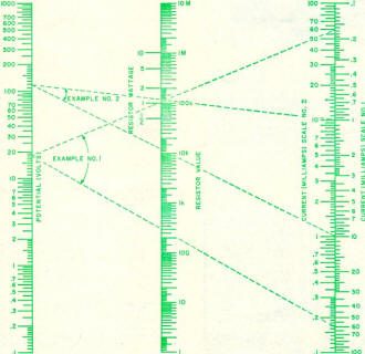
Resistance values and power dissipations may be readily determined by
the use of a straightedge.
For the man involved in the electronics field, it frequently becomes necessary
to determine the value of a resistor and wattage. The nomogram below was designed
to give the resistor value and its wattage simply by placing a straightedge from
the potential scale to the proper current scale and reading the answer on the Resistor
Value Scale or the Wattage Scale.
It will be noted that there are two current scales on the nomogram. They are
listed as Current (Milliamps) Scale No. 1 and Current (Milliamps) Scale No.2. Scale
No.1 is used only when determining the value of the resistor. Scale No. 2 is used
for determining the wattage of the resistor.
Following are two examples illustrating the use of the nomogram.
Example No.1: It is found that a cathode bias resistor is burned out and no schematic
is available. Total current of the tube - rated at 60 mA. Grid bias is -18 volts.
Determine the value, in ohms, and wattage of the resistor.
Solution: Extend a straight line from 18 on the Potential Scale to 60 on the
Current Sca1e No. 1. Read the value of the resistor at the intersection of this
line with the Resistor Value Scale as 300 ohms. To determine the wattage, extend
another line from 18 on the Potential Scale to 60 on the Current Scale No. 2. At
the intersection of this line with the wattage scale, read the answer as slightly
over 1 watt. Since the value is higher than 1, use the next higher value, namely
2 watts.
Example No.2: Determine the value, in ohms, and wattage of a resistor under the
following conditions: Voltage is measured at 117 volts, current at 10 mA.
Solution: Extend a straight line from 117 on the Potential Scale to 10 on the
Current Scale No. 1. At the intersection of this line with the Resistor Value Scale
read the value as 11.7 kohms. To determine the wattage, extend another line from
117 on the Potential Scale to 10 on the Current Scale No.2. At the intersection
of this line with the Resistor Wattage Scale, read the answer as just over 1 watt.
Assigning the next highest value, the answer then becomes 2 watts.
Nomographs / Nomograms Available on RF Cafe:
-
Parallel Series Resistance Calculator -
Transformer Turns Ratio Nomogram -
Symmetrical T and H Attenuator Nomograph -
Amplifier Gain Nomograph -
Decibel
Nomograph -
Voltage and Power Level Nomograph -
Nomograph Construction -
Nomogram Construction for Charts with Complicating Factors or Constants
-
Link Coupling Nomogram -
Multi-Layer Coil Nomograph
-
Delay Line Nomogram -
Voltage, Current, Resistance, and Power Nomograph -
Resistor Selection Nomogram -
Resistance and Capacitance Nomograph -
Capacitance Nomograph -
Earth
Curvature Nomograph -
Coil Winding Nomogram -
RC Time-Constant Nomogram -
Coil Design
Nomograph -
Voltage, Power, and Decibel Nomograph -
Coil Inductance Nomograph -
Antenna Gain Nomograph
-
Resistance and Reactance Nomograph -
Frequency / Reactance Nomograph
Posted July 13, 2021
(updated from original post on 3/18/2012)
|


