|
June 1946 Radio-Craft
 [Table of Contents] [Table of Contents]
Wax nostalgic about and learn from the history of early electronics.
See articles from Radio-Craft,
published 1929 - 1953. All copyrights are hereby acknowledged.
|
Even in this current age of ubiquitous
computers and cellphones (also computers), there is still ample reason to consider
using nomographs for presenting data and providing a hand calculation or conversion
resource. In days prior, nomographs were an indispensible tool for both design and
troubleshooting circuits. A huge number of nomographs can be found here on RF Cafe
as they appeared in vintage magazine articles. This 1946 issue of Radio-Craft presents
the first of a two-part tutorial on creating nomographs for any purpose, and uses
current, voltage, and resistance as an example. Their utility is not limited to
electrical and electronic topics, as many have been created for plumbing, hydraulics,
mechanics, chemistry, finance, aerodynamics, pneumatics, lighting, acoustics, and
I've even seen one for
earthquakes. Part II covers "Charts with Complicating Factors
or Constants."
Part I - Nomograph for Current, Voltage and Resistance
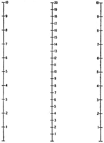
Fig. 1 - The fundamental type of nomogram.
By Fred Shunaman
A Nomogram (Greek: A new written down) is a chart made up of a number of lines
calibrated to represent quantities in the problems to be solved. A straight edge
is laid across two of the lines. The answer to the problem is found where it intersects
a third line. Most of the commonest radio problems can be put into nomograph form,
hence this type of chart is one of the most useful to radiomen.
This principle of the nomograph is simplicity itself. Fig. 1 shows a typical
one, for adding figures from 1 to 10. The outside lines which represent the numbers
to be added, may be 10 inches long, divided into equal parts (inches). The totals
are found on a line drawn midway between the two.
To calibrate the center line, lay a ruler across the tops and bottoms of the
two outside ones. Because 0 plus 0 = 0, the base of the center line is 0. At the
top, 10 plus. 10 = 20, and the line is so marked. Dividing the center line equally
gives us 20 divisions spaced one-half inch apart. If a ruler is now placed across.
the two 5's on the outside lines, the sum 10, will be read on the center one. Try
5 plus 8 or 9 plus 1.
The reader will find it very helpful to actually construct such a nomogram. The
important point to note is that the center line has twice as many divisions as the
two outside ones. That is why their sum is found on it.
The addition nomogram may be mildly interesting. It is hardly useful - it is
easier to do the additions mentally than to use the chart. The nomogram becomes
valuable when applied to equations like the familiar
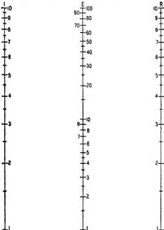
Fig. 2 - Most nomograms are forms of this one.
Such application is possible because multiplication and division can be transformed
into addition and subtraction by means of logarithms.
Most radiomen understand logarithms. To those who do not, it is enough to say
they are numbers so proportioned to ordinary numbers that the sum of the logarithms
of any two numbers is equal to the logarithm of their product. For example, adding
the logarithm of 5 to the logarithm of 6 gives the logarithm of 30. If we construct
a chart like that of Fig. 1, using the logarithms of numbers from 1 to 10, we have
a nomogram that can multiply.
Construction of Nomograms
Nomograms for all radio uses can be constructed with the help of a small supply
of logarithmic cross-section paper, which can be bought at almost any stationery
or draftsman's supply house. It is well to get a few sheets of "1 cycle X 10 divisions
per inch" as well as a smaller number of 2-cycle and 3-cycle sheets (also 10 divisions
per inch). Some tracing paper completes the outfit. Lacking logarithmic paper, a
cheap slide-rule may be pressed into service. (The slide-rule is a perfect example
of a logarithmically divided scale.)
Simplest of all multiplication nomograms is the product of two whole numbers-the
logarithmic equivalent of Fig. 1. A chart for the common radio equation IR = E (Ohm's
Law) is set up in Fig. 2. The easiest way to construct it is to fasten a piece of
tracing paper over one of the 1-cycle log sheets and trace each of its vertical
border lines. You will then have two lines about 10 inches high and 7 inches apart.
Draw the base-line and erect on it a vertical center line half-way between the other
two. Number your two outside lines according to the scale beneath the tracing paper.
Mark the two outside lines I and R, and the center line E. (I X R = E).

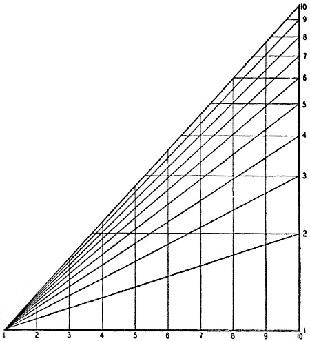
Fig. 3 - With this guide (on 10- or 20-inch paper) nomograms
may be drawn to any scale.
Next step is to calibrate the center line. The bottom number on each outside
scale is 1. Therefore the center scale at the base line is 1 X 1 = 1. The top of
the center line is 10 X 10, or 100. Insert a 2-cycle sheet under the tracing paper,
and line the base lines up with each other. You will find the 1 and 100 in the correct
positions, and can fill in the other divisions by tracing.
With this chart, the current through or voltage across any resistor between 1
to 10 ohms or 1 to 10, amperes and 1 to 100 volts can be calibrated.
A Practical Chart
Our nomogram still seems to, be of little use-the range is altogether too limited,
and these simple problems are easier done in the head. It is not altogether useless,
though its main purpose is to show how a nomogram works, before introducing more
complicated ones. Its range can be extended by multiplying or dividing either of
the factors I or R by any number (most conveniently 10) and doing the same with
the center scale. Or one outside scale can be multiplied by and the other divided
by the same number, leaving the center scale unchanged.
One of the great advantages of the nomograph is direct reading, so such tricks
are not worth while. We can make a satisfactory chart by extending the two outside
scales. Let us make one with the I and R scales on 2-cycle paper, giving them a
range of 100 to 1 instead of 10 to 1. We can further increase the range by using
two sets of figures for each I and R scale, giving us. in effect two nomograms on
the same sheet of paper.
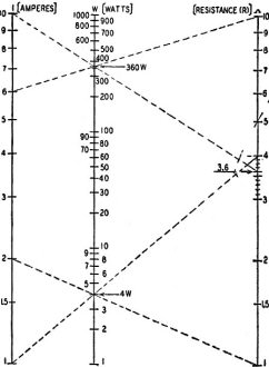
Fig. 4 - Placing the "product" scale in graphs which employ roots
or powers of the factors.
In Nomogram A, (shown on opposite page), one of the ranges (figures to the right
of the scale lines) is 10 microamperes to one milliampere (1/100,000 to 1/1,000
ampere) and 10,000 ohms to 1 megohm. The other range (figures to the left of the
scale lines) is ·from 1 milliampere to 0.1 ampere and from 100 to 10,000 ohms.
Since our outside scales range from 1 to 100, the center voltage scale might
be expected to start with 1 (1 X 1) and end with 10,000 (100 X 100). But the two
outside scales in this nomogram have been intentionally started with numbers which,
have a product of 0.1 volt. At the top we have 1 megohm X 1 ma and 10,000 ohms X
0.1 ampere = 1,000 volts in each case. How is the center scale to be constructed?
Four-cycle paper is not easily obtained - if at all - in our small size, and the
center scale has four cycles.
The device in Fig. 3 solves the problem. This is drawn on 1-cycle paper (or can
be drawn on any piece of paper more than 10 inches square with the help of a slide-rule
scale). The base is divided into 10 equal parts from 1 to 10 (conveniently 1 inch
apart). The altitude is divided logarithmically according to the 1-cycle paper (or
the C-scale of a slide-rule). (Much log paper comes seven inches wide and it may
be necessary to paste two sheets together, but carefully!) We can make logarithmic
scales of any length with this diagonal figure.
To use the diagonal guide on the 4-cycle voltage scale, mark out the 10-volt
and 100-volt points on the nomogram. One milliampere X 10,000 ohms = 10 volts. Since
these figures appear on both scales, it is necessary only to connect the values
together with the usual straightedge, marking the point where it crosses the center
line. The two marks should coincide at the 10-volt point. Locate the 100-volt point
with 10,000 ohms X 0.001 ampere and 1,000 ohms X 0.1 ampere, and the 1-volt point
with 100,000 ohms X 10 μa and 100 ohms X 0.01 ampere.
Insert the diagonal guide under the tracing paper, keep its base line directly
under the base line of the nomogram, and slide it left till the diagonal line representing
10 coincides with the 1-volt mark on the voltage scale. The cross lines from 2 to
9 - representing tenths of a volt - can now be marked off. Move the guide up and
mark the scale from 1 to 10, from 10 to 100 and from 100 to 1,000 in the same way.
 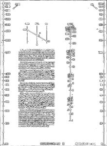
Nomogram A
Nomogram B
(Note: The originals were terrible with mottled blue backgrounds)
This nomogram can be used for any problem where two of the quantities given on
the chart are known and the third one is to be found. It has range enough to cover
most radio needs, but can be extended still further by using the right side of one
outside scale against the left side of the other, multiplying or dividing the middle
scale by the appropriate number.
More Difficult Problems
Most nomograms express more complex problems than the simple IR = E just described.
A common radio problem is: "With a given amount of current through (or voltage across)
a resistor, what is a safe wattage rating?" The mathematical formula is I2R
= W (watts). The difference between this and IR = E is that we have a power of a
number to contend with. I2 cannot be handled like simple I, but is easy
to deal with on a nomographic chart. Multiplication is expressed logarithmically
on the chart by simple addition. Powers are expressed by multiplication. The scale
for I2 is simply I X 2, or twice as long as a scale for I would be. I4
would be four times as long.
Nomograms can be constructed with scales of different lengths, but are clumsy.
There is another way out of the difficulty. Let us layout a simple nomogram on 1-cycle
paper (Fig. 4), with I and R both running from 1 to 10, in amperes and ohms or any
multiple or submultiple. The bottom figure for wattage will be 12 X 1
watt, and the top figure 102 X 10, or 1,000 watts. Thus the center scale
will have 31 cycles instead of 2 as in the straight multiplication charts.
But it will not be in the center. To locate this scale, we have to compute a
few wattages, choosing them so the lines on which they lie cross at a broad angle.
We can try 4 watts as a first attempt. This is 12 amperes X 4 ohms, or
22 amperes X 1 ohm. Draw both lines, as shown in the figure. Then find
a similar point near the top of the scale, say, 360 watts. This is 62
amperes X 10 ohms, or 102 amperes X 3.6 ohms. Drawing these two lines
to locate the 360-watt point, we find it directly above the 4-watt intersection.
A vertical line can he drawn through the two points and calibrated in 3 cycles from
3-cycle paper or the diagonal guide.
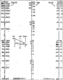
Nomogram B, shown on page 628, is suitable for calculating safe dissipation for
all bleeder resistors and line cords. Note that a safety factor of 100 percent is
allowed. If 20 watts is required, use a 40-watt resistor. The scales are 100 to
10,000 ohms and 10 milliamperes to 1 ampere. The watts scale would normally have
six cycles, but since we are not often interested in wattages greater than 1,000
and less than 0.1 watt, only four cycles are drawn. The watts scale is located as
in Fig. 4, the 1-watt and 100-watt point being particularly convenient to locate.
Easiest way to make this nomogram is to draw the outside lines 20 inches long and
use a piece of 3-cycle paper to calibrate the watts scale.
Many other radio problems are capable of easy and continuous solution with nomograms.
Part II of this article will describe constructions where reciprocals, square roots
and additional constant factors are included in the problem, and will give nomograms
for resistance of wires R = kl/C.M. and for inductance and capacity required to
tune to a given frequency f = 1/6.28 √LC.
Posted September 17, 2021
Nomographs / Nomograms Available on RF Cafe:
-
Parallel Series Resistance Calculator -
Transformer Turns Ratio Nomogram -
Symmetrical T and H Attenuator Nomograph -
Amplifier Gain Nomograph -
Decibel
Nomograph -
Voltage and Power Level Nomograph -
Nomograph Construction -
Nomogram Construction for Charts with Complicating Factors or Constants
-
Link Coupling Nomogram -
Multi-Layer Coil Nomograph
-
Delay Line Nomogram -
Voltage, Current, Resistance, and Power Nomograph -
Resistor Selection Nomogram -
Resistance and Capacitance Nomograph -
Capacitance Nomograph -
Earth
Curvature Nomograph -
Coil Winding Nomogram -
RC Time-Constant Nomogram -
Coil Design
Nomograph -
Voltage, Power, and Decibel Nomograph -
Coil Inductance Nomograph -
Antenna Gain Nomograph
-
Resistance and Reactance Nomograph -
Frequency / Reactance Nomograph
|