|
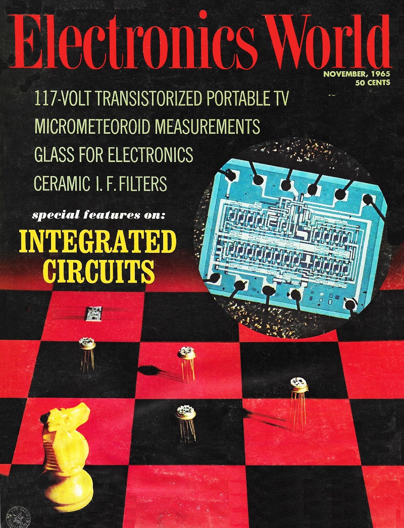
November 1965 Electronics World
 Table of Contents
Wax nostalgic about and learn from the history of early electronics. See articles
from
Electronics World, published May 1959
- December 1971. All copyrights hereby acknowledged.
|
Nomograms (aka
nomographs) have always been a great method of providing a quick visual means of
relating various quantities to each other. Careful adjustment of the numerical
scales allows a straight line to be drawn between any two values to determine
the value of the third (or more). An extreme example is the
Link
Coupling Nomogram which uses two straight line scales and a curve graph. As can be seen in this Transformer Turns Ratio
Nomogram from a 1965 issue of Electronics World magazine, a square root function
(TR=√Z1/Z2) can be easily accommodated with a straight
line from the input impedance scale to the output impedance scale, and extending
it to the third turns ratio (TR) scale. A similar nomogram can be constructed
for turns ratio needed for specific input and output voltage, current, or power.
A list of many other nomographs/nomograms is given at the bottom of the page.
Transformer Turns Ratio Nomogram
 By Max H. Applebaum By Max H. Applebaum
Warwick Electronic Inc., Pacific Mercury Div.
Simple method of determining the turns ratio for transformers employed for impedance
matching.
This nomogram aids in the computation of the turns ratio for transformers used
for impedance matching. The basic equation for the turns ratio is T.R. = √Z1/Z2, where Z1 is the primary impedance, Z2 is the secondary
impedance, and T.R. is the turns ratio N1/N2.
The method of solution is illustrated in the example below.
Values other than those shown on the scales may be used by multiplying them by
10n where n may be positive or negative. If Z1 and Z2 are both multiplied
by 10n, then T.R. remains unchanged. If only Z1 is multiplied by 10n,
then T.R. is multiplied by 10n/2. If only Z2 is multiplied by 10n,
then T.R. is multi-plied by 10-n/2. Using even values of n will simplify
the con-version of scales.
Example: Find the turns ratio required for an audio output transformer to match
a plate impedance of 500,000 ohms to a speaker whose impedance is 8 ohms.
Solution, Draw a straight line from 5000 on the Z1 scale to 8 on the Z2 scale.
The line crosses the T.R. scale at 25. Since Z1 was multiplied by 100 then T.R.
must be multiplied by 10. The turns ratio is therefore 250/1.
Posted December 22, 2022
Nomographs / Nomograms Available on RF Cafe:
-
Parallel Series Resistance Calculator -
Transformer Turns Ratio Nomogram -
Symmetrical T and H Attenuator Nomograph -
Amplifier Gain Nomograph -
Decibel
Nomograph -
Voltage and Power Level Nomograph -
Nomograph Construction -
Nomogram Construction for Charts with Complicating Factors or Constants
-
Link Coupling Nomogram -
Multi-Layer Coil Nomograph
-
Delay Line Nomogram -
Voltage, Current, Resistance, and Power Nomograph -
Resistor Selection Nomogram -
Resistance and Capacitance Nomograph -
Capacitance Nomograph -
Earth
Curvature Nomograph -
Coil Winding Nomogram -
RC Time-Constant Nomogram -
Coil Design
Nomograph -
Voltage, Power, and Decibel Nomograph -
Coil Inductance Nomograph -
Antenna Gain Nomograph
-
Resistance and Reactance Nomograph -
Frequency / Reactance Nomograph
|