|
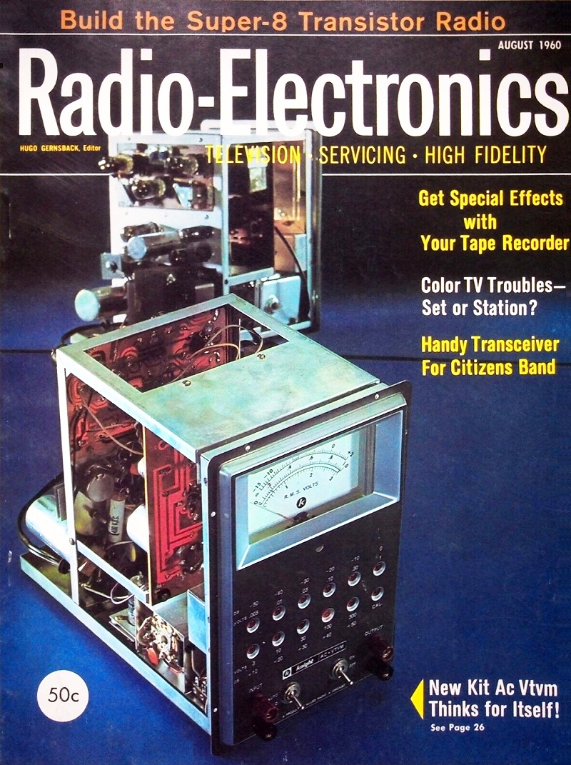
August 1960 Radio-Electronics
 [Table of Contents] [Table of Contents]
Wax nostalgic about and learn from the history of early electronics.
See articles from Radio-Electronics,
published 1930-1988. All copyrights hereby acknowledged.
|
Nomographs for calculating
and converting values for resistance, capacitance, inductance, transformer coupling,
frequency and wavelength, path loss, resonant frequency, AC impedance, and
other parameters appeared in many magazines over the decades. In the days before
handheld electronic calculators and, nowadays, smartphones, the use of a nomograph
provided rapid solutions for sometimes complex mathematical equations. This particular
nomograph calculates resistor values in series and parallel, where two resistors
are combined to yield the required resistance. Series resistances are a simple matter
of addition, but parallel resistance requires combinations of addition, multiplication,
and division. Multiplication and division could be carried out with the help
of a slide rule, but addition was still done by hand (slide rules don't do addition or
subtraction). A unique feature of this particular "Parallel Series Resistance Calculator"
from the August 1960 issue of Radio-Electronics magazine is the inclusion of a straight edge component for cross-referencing the two scales
on the chart. While it might seem clever, using it as provided covers part of the
chart, compromising accuracy. I suggest either not using the connector (just use
a ruler), or fold it in half lengthwise along the black line, then aligning that
edge with the vertical side scales.
Parallel Series Resistance Calculator
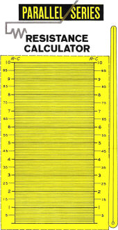
Full-size diagram you can cut out and mount to make your own
calculator.
By S. J. Salva
One of the biggest headaches in electronic work is having to break off in the
middle of a job to figure values for parallel resistance or series capacitance.
The calculator described here eliminates much of this pencil and paper work-thereby
saving time and the aspirin supply.
How to use the calculator.
The value of any two resistors in parallel or any two capacitors in series can
be found by setting the first value on the left scale with the right indicator arm
and the second value on the right scale with the left arm. The answer is read at
the intersection of the two arms. By using standard multipliers, x 10, x 100, etc.,
the full range of values can be covered.
In Fig. 1, for example, to determine the value of an 800- and a 700-ohm resistor
connected in parallel, we set the right arm to indicate 800 on the left scale. Then
we set the left arm at 700 on the right scale, and the answer is read as 370 ohms.
The calculator is easily constructed. Simply cut any light sheet of material
to the size of the chart - plastic, or even cardboard will do - and glue the chart
(Fig. 2) in place. Using clear plastic or celluloid of thin stock, construct two
arms similar to the one in the drawing. A straightedge and a sharp nail should be
used to scribe a line down the center of each arm. Rub a bit of India ink into the
scribed lines, wipe off the excess, and you have a couple of first-class indicators.
The arms are attached to the board as shown in Fig. 1. Small rivets or eyelets will
serve for this.
The calculator's size limits accuracy to about 2%. In circuits where greater
accuracy is required, it will still be necessary to use the formulas, or make a
bigger calculator!
Posted March 8, 2023
Nomographs / Nomograms Available on RF Cafe:
-
Parallel Series Resistance Calculator -
Transformer Turns Ratio Nomogram -
Symmetrical T and H Attenuator Nomograph -
Amplifier Gain Nomograph -
Decibel
Nomograph -
Voltage and Power Level Nomograph -
Nomograph Construction -
Nomogram Construction for Charts with Complicating Factors or Constants
-
Link Coupling Nomogram -
Multi-Layer Coil Nomograph
-
Delay Line Nomogram -
Voltage, Current, Resistance, and Power Nomograph -
Resistor Selection Nomogram -
Resistance and Capacitance Nomograph -
Capacitance Nomograph -
Earth
Curvature Nomograph -
Coil Winding Nomogram -
RC Time-Constant Nomogram -
Coil Design
Nomograph -
Voltage, Power, and Decibel Nomograph -
Coil Inductance Nomograph -
Antenna Gain Nomograph
-
Resistance and Reactance Nomograph -
Frequency / Reactance Nomograph
|