|
Dec. 1931 / Jan. 1932 Short Wave Craft
 [Table
of Contents] [Table
of Contents]
Wax nostalgic about and learn from the history of early electronics. See articles
from Short Wave Craft,
published 1930 - 1936. All copyrights hereby acknowledged.
|
This is a
nice short article covering the calculation of inductances for coils wound on cores
and wire sizes. It appeared in a 1932 issue of Short Wave Craft magazine, but of
course inductance has not changed since then so it is still relevant. The author
recognized that standard formulas, although concise and accurate, are sometimes
difficult to work with when calculations for a large number of values is needed
for a particular circuit design. To address the situation, he presents a handy nomograph,
chart, and a table of typical values. He also introduces a rarely seen term "Nagaoka's
correction factor*" for skin effect. A smartphone app, a spreadsheet, or a desktop
computer program would be used today to calculate inductance values, number of turns,
winding spacing, etc., but back when mechanical slide rules were the order of the
day, these visual methods were a real benefit.
* "The Inductance Coefficients of Solenoids,"
Hantaro Nagaoka,
1909
How Many Microhenrys in That Coil?
By James K. Clapp*
Every radio student should know how to calculate the inductance
of a coil of given or known size. Here's a simplified method worked out by a leading
engineer.
|

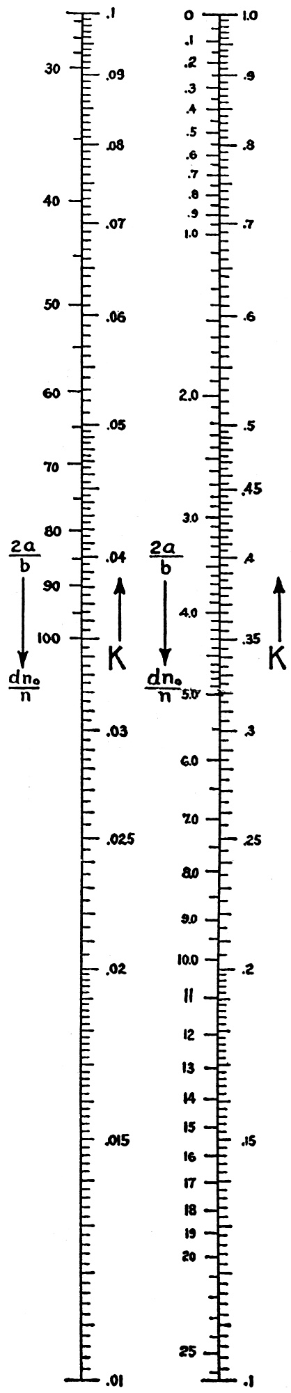
Fig. 3 - This nomograph gives the values of Nagaoka's
constant "K" for different values of 2a over b = dn0 over n, on a logarithmic
scale. This chart will prove very useful in calculating the inductance of coils.
|
While much material has been published on the calculation of the inductance of
coils†. the formulae given are in general not convenient for engineering use. Two
difficulties are encountered in applying the results in engineering practice, one
being the involved computations and the other the fact that differences in form
and wire sizes and errors in the measurement of these factors introduce errors in
the calculations which largely vitiate the utility of precise formulae.
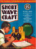
Fig. 1 - The inductance of coils closely wound on General
Radio, type 577 form, as a function of the number of turns and different sizes of
double-silk covered wire. Table I gives number of turns.
For single-layer coils at radio frequencies (and, with slight modification, for
bank-wound coils), Nagaoka's formula probably is the best for general engineering
use. While neglecting the shape and size of the cross-section of the wire, the self-capacity
of the winding and the variation of inductance due to skin-effect, it may be shown
that the formula gives about as good results for high-frequency inductance as can
be obtained.
Tables of the values of Nagaoka's correction factor have been prepared, but require
considerable time to use due to the necessity for interpolations. The table values
may be plotted in the form of a curve, but a more convenient interpolation is made
possible by plotting these values on logarithmic scales, as has been done in Figure
3. Where much work of this type is done, the scales may be transferred to a slide-rule
so that no reference to printed material is required.
The formulae given here, when carefully applied, give values of inductance to
within about two per cent for single-layer coils and to within about five per cent
for four-layer bank-wound coils for frequencies where the coils would serve as normal
tuned-circuit elements.
The general formula is 
where a is radius of a mean turn in inches, n is the number of turns, b is the
length of the winding in inches, and K is Nagaoka's correction factor which is a
function of  or the ratio of
diameter to length of the winding. or the ratio of
diameter to length of the winding.
If n0 is the number of turns per inch, the inductance and ratio of
diameter to length are more conveniently given by:
L = 0.1003 * a2 * n * n0 * K, microhenrys (2)
or L = 0.0251 * d2 * n * n0 * K, microhenrys (3)
where  numeric (4) numeric (4)
and d is the diameter of the mean turn in inches.
Given the size of wire and its insulation and the diameter of the coil form,
n0 as wound, is found from Table I and
 is readily computed for
any desired number of turns. Read the corresponding value of K from the scales at
the left. The inductance is then easily computed by means of the slide-rule. is readily computed for
any desired number of turns. Read the corresponding value of K from the scales at
the left. The inductance is then easily computed by means of the slide-rule.
For banked windings of not too great depth as compared with the diameter, a close
approximation for the inductance is obtained by using Nn0 for the turns
per inch (where N is the number of banks) and
 for the ratio of diameter
to length. for the ratio of diameter
to length.
Then =
numeric (5) and L = 0.0251
* d2 * N * n * n0 * K,
microhenries (6)
Fig. 2 - Inductance of coils wound on General Radio, type
577 form, with double silk covered, copper wire, in which the turns have been equally
spaced in order to fill the 2-inch winding space. Here n0 = 1/2 n.
The number of turns required for a desired value of inductance cannot be directly
calculated since K varies as n is varied. With given types of windings experience
will indicate an approximate value for the number of turns. If the computations
are carried out and the inductance obtained is near the desired value, the correct
number of turns to give the desired value may be obtained by readjustment, since
K does not vary rapidly with n. Where many values are required it is simpler to
calculate a sufficient number of values for a curve. The required values may then
be read off directly. (See Figures 1 and 2, for example.)
Examples of Calculations
Given: Form diameter = 2.75 inches (General Radio Company Type 577 Form). Wire
size = No. 20 double-silk-covered. Find: The inductance for coil of 35 turns.
Procedure: In Table 1 find n0 = 25

From scales, opposite 1.99 for , read
K= 0.526
L = 0.0251 * (2.79)2 * 35 * 25 * 0.526 = 90.0 microhenries.
For a rough estimate, the diameter of the form may often be taken as the diameter
of a turn. In the above example this procedure gives
= 1.965, K = 0.530 and
L = 88 microhenries, which differs from the previous value by about 2.5 per cent.
For bank-wound coils an example is as follows:
Given: d = 2.75, n0 =25, N = 4, and n = 200
Then = 1.455.
From Figure 3, K = 0.604
Then  4 x 25 x 200 x 0.604 = 2570 microhenries. 4 x 25 x 200 x 0.604 = 2570 microhenries.
Table I - Winding Data for Closely Wound Coils
Many experimenters and many engineers "design" inductors by guessing at the number
of turns, then peeling off wire until the correct value of inductance is obtained
rather than go to the trouble of using the usual tables and formulas. Our experience
with the method described here proves conclusively that much time and effort are
saved by calculating the desired value of inductance before the coil is wound. -
Courtesy "General Radio Experimenter."
*Engineer, General Radio Company
†See in particular the publications of the U. S. Bureau of Standards and
the Proceedings of the Institute of Radio Engineers.
Posted September 6, 2023
(updated from original post
on 12/23/2015)
Nomographs / Nomograms Available on RF Cafe:
-
Parallel Series Resistance Calculator -
Transformer Turns Ratio Nomogram -
Symmetrical T and H Attenuator Nomograph -
Amplifier Gain Nomograph -
Decibel
Nomograph -
Voltage and Power Level Nomograph -
Nomograph Construction -
Nomogram Construction for Charts with Complicating Factors or Constants
-
Link Coupling Nomogram -
Multi-Layer Coil Nomograph
-
Delay Line Nomogram -
Voltage, Current, Resistance, and Power Nomograph -
Resistor Selection Nomogram -
Resistance and Capacitance Nomograph -
Capacitance Nomograph -
Earth
Curvature Nomograph -
Coil Winding Nomogram -
RC Time-Constant Nomogram -
Coil Design
Nomograph -
Voltage, Power, and Decibel Nomograph -
Coil Inductance Nomograph -
Antenna Gain Nomograph
-
Resistance and Reactance Nomograph -
Frequency / Reactance Nomograph
|