|
Plenty of single-layer
coil (inductor) winding calculators, charts, and nomographs can be found on the
World Wide Web, but finding one for multi-layer coils is a bit harder - until
now. Actually, this Multi-Layer Coil Calculator Nomograph appeared in a 1955 issue
of Radio & Television News magazine. It was an era long before personal
calculators, computers, and smartphones, when long-hand written-out problem solving
was the norm, and slide rules made such tasks easier for those fortunate enough
to know how to work one. I did a little head scratching upon encountering the
term "no. 27 d.c.c. wire," not being familiar with the "d.c.c." part. A little research
turned up that it means "double cotton covered" for insulation, and there was also
"s.c.c." for single cotton covered. Belden and Alpha used to make it. Enamel-covered
wire is now used for winding coils and transformers. As you might expect, some companies
who specialize in replicating vintage components still make the
cotton-covered wire
(here's another), or at least something
that looks like it but is better quality.
Multi-Layer Coil Calculator Nomograph
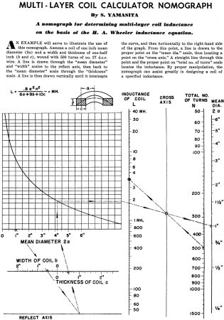 By S. Yamasita By S. Yamasita
A nomograph for determining multi-layer coil inductance on the basis of the H.
A. Wheeler inductance equation.
An example will serve to illustrate the use of this nomograph. Assume a coil
of one inch mean diameter (2a) and a width and thickness of one-half inch (b and
c), wound with 500 turns of no. 27 d.c.c. wire. A line is drawn through the "mean
diameter" and "width" scales to the reflect axis, then back to the "mean diameter"
scale through the "thickness" scale. A line is then drawn vertically until it intercepts
the curve, and then horizontally to the right-hand side of the graph. From this
point, a line is drawn to the proper point on the "mean dia." scale, thus locating
a point on the "cross axis." A straight line through this point and the proper point
on "total no. of turns" scale locates the inductance. By proper manipulation, the
nomograph can assist greatly in designing a coil of a specified inductance.
Posted September 30, 2021
Nomographs / Nomograms Available on RF Cafe:
-
Parallel Series Resistance Calculator -
Transformer Turns Ratio Nomogram -
Symmetrical T and H Attenuator Nomograph -
Amplifier Gain Nomograph -
Decibel
Nomograph -
Voltage and Power Level Nomograph -
Nomograph Construction -
Nomogram Construction for Charts with Complicating Factors or Constants
-
Link Coupling Nomogram -
Multi-Layer Coil Nomograph
-
Delay Line Nomogram -
Voltage, Current, Resistance, and Power Nomograph -
Resistor Selection Nomogram -
Resistance and Capacitance Nomograph -
Capacitance Nomograph -
Earth
Curvature Nomograph -
Coil Winding Nomogram -
RC Time-Constant Nomogram -
Coil Design
Nomograph -
Voltage, Power, and Decibel Nomograph -
Coil Inductance Nomograph -
Antenna Gain Nomograph
-
Resistance and Reactance Nomograph -
Frequency / Reactance Nomograph
|