|
January 1930 Radio-Craft
 [Table
of Contents] [Table
of Contents]
Wax nostalgic about and learn from the history of early electronics.
See articles from Radio-Craft,
published 1929 - 1953. All copyrights are hereby acknowledged.
|
 January 1930 was very shortly after the major
stock market crash in October of the previous year, so a lot of people suddenly
were not motivated to buy unnecessary creature comfort items - like radios. Many
of the smaller manufacturers were forced out of business accordingly. Fewer and
simpler designs seemed to dominate the surviving market for a couple years as
the economies of the world slowly recovered. America was not alone in the
financial doldrums. Just about the time things were rolling along merrily again,
a short-tempered little guy with a funny mustache decided he wanted to rule over
all of Europe, starting a war that would eventually cause nations to dedicate
manufacturing facilities and materials for radios (and many other things) to
weapons production. Non-military radio production was suspended from 1942
through 1945. After that, electronics for all manner of entertainment grew
exponentially. The
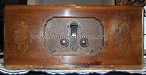
photo of the Bremer-Tully Model 7-70 radio was found on the RadioMuseum.org
website. It looks like a very basic tabletop configuration. January 1930 was very shortly after the major
stock market crash in October of the previous year, so a lot of people suddenly
were not motivated to buy unnecessary creature comfort items - like radios. Many
of the smaller manufacturers were forced out of business accordingly. Fewer and
simpler designs seemed to dominate the surviving market for a couple years as
the economies of the world slowly recovered. America was not alone in the
financial doldrums. Just about the time things were rolling along merrily again,
a short-tempered little guy with a funny mustache decided he wanted to rule over
all of Europe, starting a war that would eventually cause nations to dedicate
manufacturing facilities and materials for radios (and many other things) to
weapons production. Non-military radio production was suspended from 1942
through 1945. After that, electronics for all manner of entertainment grew
exponentially. The
photo of the Bremer-Tully Model 7-70 radio was found on the RadioMuseum.org
website. It looks like a very basic tabletop configuration.
Bremer-Tully Model 7-70 and 7-71 Radio Service Data Sheet
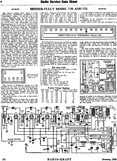 This receiver includes three stages of tuned
radio-frequency amplification, neutralized in the "Counter phase" manner. To test
this part of the circuit, a continuity tester is used to check the connections which
include, (in the circuit V1, for example), L2N, C5, and a few turns at the grid
end of L1S. The "micro-mikes" or neutralizing condensers C5, C6 and C7 are located
at the right of the respective tube sockets. This receiver includes three stages of tuned
radio-frequency amplification, neutralized in the "Counter phase" manner. To test
this part of the circuit, a continuity tester is used to check the connections which
include, (in the circuit V1, for example), L2N, C5, and a few turns at the grid
end of L1S. The "micro-mikes" or neutralizing condensers C5, C6 and C7 are located
at the right of the respective tube sockets.
The procedure of balancing a receiver using the Counterphase neutralizing method
will be described. Usually it is convenient to use a vacuum tube with one of the
filament prongs shortened so that the filament circuit is open when the grid, plate
and one side of the filament are making contact. Now, tune in a loud signal, adjusting
all tuning controls very carefully for exact resonance. Replace V3 with the special
tube. (Always start with the R.F. stage next to the detector). Retune all controls
until maximum volume is obtained. The "micro-mikes" are now adjusted. The best tool
for this purpose is a piece of bakelite rod which has been shaped to a screw-driver
edge.
Posted October 17, 2023
(updated from original
post on 10/28/2016)
Radio Service Data Sheets
These schematics, tuning instructions, and other data are reproduced from my
collection of vintage radio and electronics magazines. As back in the era, similar
schematic and service info was available for purchase from sources such as
SAMS Photofacts, but these printings
were a no-cost bonus for readers. There are 227 Radio Service Data Sheets as of
December 28, 2020.
-
AMRAD
Model 81 "Bel Canto"
-
GE
Model 250 Radio Service Data Sheet
- Hoffman
Model A300
- Emerson
Model 505
- Olympic
Models 6-501, 6-502, 6-503
- Radiola
Models 61-5, 61-10
- Farnsworth
Models ET-060, ET-061, ET-063
- General
Electric Model 321
-
Garod Model 6AU-1
- Truetone
Model D4620
- Westinghouse
Model H-148
- Wards Models
54BR-1501A, 1502A
- Majestic
Models 8S452, 8S473
- RCA Models
Q22A, Q32
- Zenith Model
5G003ZZ
- Mantola Models
92503 and 92504
- Emerson Model
508 Series 8-7434351 and Up
- Belmont Model
A-5D118
- Wards Model
74BR-2707A
- Crosley Model
56TP-L
- Admiral Model
7C60 Chassis 6B1
- 336
Belmont Radio Model 6D111, Series A
-
333 General Electric Models 100, 101, 103 and 105
- RCA Victor
Models 54B1, 54B-N, 54B2, 54B3 Radio Data Sheet 335
-
National Union "Presentation" Radio Model G-619
-
Zenith Radio Models 8H032, 8H033, 8H050, 8H052, 8H061
-
General Electric Farm Radio Model 280
-
Admiral Model 6RT44-7B1
-
Montgomery Ward Airline Model 04BR-1105A Radio
- Belmont
Model 678 Auto-Radio Set
- Sentinel
Model 217-P Portable Radio Set Radio
- Remler
Model No. 36 Dual-Wave Auto-Radio
-
Stromberg-Carlson No. 82 All-Wave Receiver
-
Majestic A.V.C. Model 290 Chassis
- FADA 9 Tube
Model 190 "Metal" All-Wave
- RCA Victor
Models 9T and K2 9-Tube, 5- to 566-Meter
-
Motorola "Golden Voice" Model
-
RCA Victor Model H-6
-
Simplex Model TA
-
Automatic "Magic Eye" Model A1
- Silvertone
Models 4488 and 4588 (Chassis No.101412) and 4488A and 4588A (Chassis No. 101412A)
- RCA Victor
Model M109 "De Luxe" 7-Tube Auto-Radio Receiver
- Crosley Model
6625 6-Tube 3-Band Receiver
- International
Model 77 Series 7-Tube Dual-Band Receiver
- Belmont
Model 6D121
-
General Electric Models 60, 62
- Admiral
Model 7C64
-
Radiola "28" Super and "104" Power Speaker
- Sonora
Model TW-49
-
Stromberg-Carlson Models 1020, 1120, Series 10
- Air King
Model 4604D
- Sparton Models
526, 526X, 526PS
- Truetone
Model D2624
- Admiral
Models 6EI, 6EIN
- Detrola Models
571A, 571B
-
General Electric Model 250
- Howard Model
920
- Colonial
Model 652 5-Tube Broadcast-Short-Wave
-
Fairbanks-Morse
9-Tube All-Wave Model 91
-
International Model 500 5-Tube Dual-Range Battery
- Emerson Model
678 "Auto-Dynamic" 5 Tube
-
Stromberg-Carlson
Nos. 230 and 231 Series
- Atwater
Kent Model 649 All-Wave
-
Howard Model G-26, and "Airplane 4" Model AA25
-
Montgomery Ward "Airline" Series 7GM 7-Tube High-Fidelity Receiver
- RCA
Victor Model T5-2 5-Tube, 2-Band A.C. Superheterodyne Receiver
-
Majestic
"Models 50," "51" and "52"
-
Bremer-Tully Model 7-70 and 7-71
-
General
Electric Model M-49 4-Tube Radio-Phonograph Dual-Wave Superheterodyne
- RCA-Victor
Radiola "Superette" Model R7 Superheterodyne
- Crosley Model AC-7
and AC-7C
-
Westinghouse
"Columnaire" Models WR-8 and WR-8-R (Remote Control)
-
Characteristics
of Metal Tubes - and Other "Octal" (8-Prong) Base Types
- Kolster K20,
K22, K25, K27 and K37 Six-Tube Receivers
-
Stromberg-Carlson
Nos. 62 and 63, 8-Tube High-Fidelity Chassis
- RCA Model
103, 4-Tube A.C. Compact Dual-Wave
- FADA "Special"
Model 265-A and FADA "7" Model 475-A
-
General Electric Model C-62 6-Tube Battery
- Emerson
5A Automotive
- Zenith
666 Automotive
- Motorola
100 Automotive
-
Crosley
Roamio 4-A-1 Automotive
-
American-Bosch
524A Automotive
- Crosley
Model 1316 (in Model 167 Console)
- RCA Victor
"High-Fidelity Electrola," Model R-99
- AMRAD
Model 81 ("Bel Canto" Series) Receiver
-
Fada 103 Fadalette, Stewart-Warner Series 108, DeWald 54 Dynette Sets
- RCA
Victor R-27 and Philco 53 Ultra-Midget A.C.-D.C. Radio Receivers
-
Majestic Models Fairfax and Sheffield 8-Tube
- Stromberg-Carlson
No. 29, 9-Tube Superhet
-
International Kadette Model 400 4-Tube Battery-Operated Superhet
- RCA Victor
Model 5M 5-Tube Auto Superhet
-
Majestic Model 11 Short-Wave Converter
-
Silver-Marshall
Model 727-DC Battery-Operated Superheterodyne
- RCA
Victor Model VHR-307 Home Recording - Phono-Radio Combination
-
Delco 32-Volt Radio Receiver Chassis Models RA-3, RB-3 and RC-3
- Majestic
Chassis Models 380 A.C. T.R.F., and 400 A.C.-D.C. Superheterodyne
- General
Motors S1A, S1B
- Admiral
Model 7C63, Chassis 7C1
- Westinghouse
Model H-133
- Arvin
Models 150TC, 151TC
- Kadette Model
90 Duplex
-
RCA-Victor "Magic Brain" Model 281
- Grunow
11A Chassis 11-Tube All-Wave Superheterodyne
-
Sears, Roebuck & Co., Silvertone "Rocket" Models 6110 and 6111
-
General Electric Model GD-52
-
Zenith Models 6D302, 6D311, 6D326, 6D336, 6D360
-
Allied Radio, Knight Model E10913
- Arvin Model
140P
- Emerson
Models 501, 502, 504
- Crosley
Model 56TD-W
- Hoffman
Model A500
-
Stewart-Warner
Model 9003-B
-
Zenith Models 6D014, 6D029
- Coronet
Model C-2
- Sparton
Models 7-46, 7-46PA, 8-46, 8-46PA
-
Stewart-Warner Models 9001-C, D, E, F
-
Zenith Models 5D011-5D027
- Bendix Models
636A, C, D
- ECA Model 108
-
International Model 66 and 666, 6-Tube Superhet
-
Ford-Philco
Radio, Model FT9, 6-Tube Auto-Radio Receiver
- Howard
Explorer Model W Deluxe 19 Tube All-Wave Superhet
- RCA Victor
Portable Table Electrola Model R-95
- Atwater
Kent Model 305Z 5-Tube 32 V. D.C. Superhet
- Kadette
Jewel Model 40 Chassis 3-Tube Ultra-Midget Receivers
-
General Electric Model N-60 6-Tube Auto Superheterodyne
-
Sparton Model 40 6-Tube T.R.F. Automotive Receiver
-
Clarion "Replacement" Chassis, Model AC-160 A.V.C. Superheterodyne
- Emerson Models
20A and 25A
- General
Electric K-40A
- Pilot Model
B-2
- RCA-Victor
Radiola Model M-30 Automotive Radio
- Motovox
Models 10A All-Electric and 10E Battery-Operated "Moto-Tetradynes"
-
Kennedy Superheterodyne Short-Wave Converter
- RCA
Victor Model R-78 B1-Acoustic 12-Tube
- Philco
Model 15 Series, 11-Tube Superheterodyne Chassis
-
Zenith Challenger Model 740
-
Sparton
Selectronne Receivers Models 1068 and 1068X
- Fada Model
155 Super Fadalette A.C.-D.C. Set
-
Clarion De Luxe Models AC-280 and 25-280
-
Crosley Model A-157 (River Roamio) Auto Radio
- Philco Model
'37-116 Codes 121 (Shadometer) and 122 (Dial Tuning)
-
Arvin Model 28
-
Philco Model 818
-
Fada Model 266 Motoset
-
Bosch Models 736, 737, 738
- RCA-Victor
Model 15U, Radio-Phonograph
- Sparton
Models 566 ("Bluebird" Mirror), A.C.-D.C. 5-Tube 2-Band Midget Superhet
- Atwater
Kent Model 776 6-Tube Auto Radio
- Stromberg-Carlson
No. 61 4-Band 7-Tube A.C.-D.C. Receiver
- Arvin Model
182TFM
- Crosley
Model 58TK
- Westinghouse
Model H-165
-
General Electric Models G-105 and G-106
- Silvertone
"F," "FF," "G," "H," and "J"
-
Stewart-Warner Model 03-5A1 to 03-5A9 (Chassis 03-5A) Senior Varsity Radio
- Radiola Models
61-6, 61-7
-
Westinghouse
Models H-104, H-105, H-107, H-108
- Farnsworth
Models EC-260, EK-262, EK-263, EK-264, EK-265
-
United
Models 980744, 980745
-
Stewart-Warner (R-127 Chassis) Models 1271 to 1279 All-Wave
- ERLA Model
4500 Dual-Wave T.R.F. 4-Tube A.C. Receiver
- Clarion No. TC-31
5-Tube A.C.-D.C. Superhet.
- Detrola Model
105C 5-Tube Dual-Band A.C.-D.C.
- Zenith
6-Tube All-Wave Chassis No. 5634
- RCA Victor
Model 261, 555 to 107 Meter
- Philco
Model 38-116; Code 125
-
Stewart-Warner "Ferrodyne" Chassis Model R-136
-
American-Bosch
Model 43OT 5-Tube 3-Band Superheterodyne
- RCA
Victor Model C9-4 9-Tube 3-Band Superheterodyne
- Kennedy "Model
826B" Combination Receiver
- Steinite
50-A and 102-A
- Pilot Model
63 All-Wave 6-Tube Superheterodyne
- Stromberg-Carlson
No. 69 4-Tube All-Wave Superhet. Selector (Converter)
- RCA
Victor Model 102 4-Tube A.C.-D.C. T.R.F. Receiver
- Bosch Models 60
and 61
-
Atwater Kent Models 30, 33, 35, 48 and 49
- Crosley Model
120 Senior Superheterodyne (Pliodynatron) Chassis
-
Columbia Screen-Grid 8 Receiver
-
General Electric Models A82 and A87, 8-Metal-Tube All-Wave A.C. Superhet.
- Colonial
31 and 32 D.C.
- Zenith 5-Tube
Triple-Wave Chassis nos. 5508 and 5509
- Remler Model
46 ("Scottie")
- General
Electric FA-60 and FA-61
-
Stewart-Warner
Series 900
-
Howard
Model B-5 (715), Series 1 and 2 (Sheaffer Radio-Clock-Pen Desk Set)
-
Ford-Philco Car-Radio Models F-1440 and F-1442
-
Brunswick Model 31 Combination Radio and Panatrope
- Emerson Models
38, 42 and 49, 6-Tube Dual-Wave (Chassis U6)
-
General Motors Chevrolet No. 601574 Automotive
-
RCA Victor M-104 (and M-108) Automotive
- Arvin-Ford
17-A Automotive
-
Westinghouse Model WR 207 & WR 208 5-Tube Dual-Band Superheterodyne
- Radiolas
"Super VIII" (AR-810, "Semi-Portable" (AR-812), 24 and 26
- Howard Model
45 A. V. C.
- Majestic
Model 25
-
Galvin Motorola Model 61
-
Arvin Model 6
- Admiral
Models 7T06, 7T12
- Garod Model 5A1
- Hoffman Model A301
-
Knight Model E10716 Battery Portable
- Arvin Models 555,
555A, 552N, 552AN
- Grantline Models
605, 606
- Truetone Model
D2616
- Belmont Model
5D128
- Arvin Models 444,
444A
-
International Kadette Model 1019
-
Stewart-Warner Models 97-561 to 97-569
- General
Electric Model 280
- Zenith Models 5R080,
5R086
- Truetone Models
D1747, D1748
-
Crosley Roamio Automotive T.R.F. Models 90, 91, 92
-
Crosley Roamio Automotive Superheterodyne Models 95, 96
-
Wells-Gardner Series 062
-
Emerson
Model AZ-196
- Belmont Model
5P19
- Crosley
Fortyfive
- Crosley Model
56FC
-
Emerson
Models 507, 509, 518, 522, 535
- Garod Model 6AU-1
- General
Electric Models 219, 202, 221
-
Crosley "Chairside" Model 567
-
Belmont Model 408 Battery "Farm"
- Wards Model
74BR-1055A
- Farnsworth
Models EK-081, EK-082, EK-083, EK-681
- Philco
Model 200-X Radio
-
Admiral "Aeroscope" Models 161-5L, 162-5L and 163-5L
- Philco
Model 59, 4-Tube A.C. Midget Superheterodyne
- Zenith
Farm Model 6V 27, 6-Tube Superhet
- Ward 10-Tube
All-Wave High-Fidelity Superhet, Series ODM
-
Philco-Packard
Deluxe
-
Canadian
Westinghouse Model 175
- Crosley Model
1155
- Philco Models
39 and 39A
-
Arvin Model 35 8-Tube Car-Radio
- Hetro
Air-Ace Series M
- Westinghouse
Models H-161, H-168, H-168A
- Garod Model 5A4
- Arvin Models 152T,
153T
- Belmont Model 5240
- Mantola Models 92505,
92506
- General Electric
Models 102, 102W, 107, 107W, 114, 114W, 115, 115W
- Crosley Model
555 (A.F.M.)
- Crosley Model
515 (Fiver)
- Crosley Model
425 (Travo)
-
Firestone-Stewart-Warner Model R1332
- Fairbanks-Morse
Model 81 "Farm" Set
- Clarion Model
423, 470, 471, 472, 480
-
International Radio Corp. Model 90
- Belmont Model
578 Series A
|