|
July 1932 Radio-Craft
 [Table
of Contents] [Table
of Contents]
Wax nostalgic about and learn from the history of early electronics.
See articles from Radio-Craft,
published 1929 - 1953. All copyrights are hereby acknowledged.
|

Clarion Model AC-60 Tombstone Tabletop Radio (eBay image)
This Radio Service Data Sheet for the Clarion "Replacement" Chassis, Model AC-160
A.V.C. Superhet is an example of the dozens of similar schematic and alignment instruction
sheets that have been posted on RF Cafe over the years. It appeared in a 1932 issue
of Radio-Craft magazine. "Of the estimated 17 million radio sets now in
use in the United States, the chasses of approximately 11 million are now obsolete,
due to the rapid advance in receiver design." It was likely a replacement for the
c1930 Model AC-60. Obtaining technical information on most things, even readily
available items, prior to the Internet era was often very difficult - if not impossible.
Service centers had what was need provided by manufacturers and distributors, but
if you wanted to find a part number or service data on a refrigerator, radio, lawn
mower, garage door opener, etc., and did not have the original paperwork, you were
usually out of luck. Nowadays a Web search will quite often get you what you need
thanks to people (like me) who go to the trouble of making the information available.
The stuff doesn't just magically appear or get posted by benevolent governmental
entities. You're welcome.
Clarion "Replacement" Chassis, Model AC-160 A.V.C. Superheterodyne Radio Service
Data Sheet
 (Push-Pull Pentodes, Variable-Mu Tubes,
Tone Control and A.V.C.) (Push-Pull Pentodes, Variable-Mu Tubes,
Tone Control and A.V.C.)
Of the estimated 17 million radio sets now in use in the United States, the chasses
of approximately 11 million are now obsolete, due to the rapid advance in receiver
design. At the same time, the cabinets in which these chasses are housed are just
as much in vogue as the day they were bought, and they still represent a considerable
portion of the cost of the ensemble.
To offset this discrepancy, a western manufacturer has brought out a 10-tube
super-heterodyne receiver chassis, complete in every respect, and modern in design,
which is to be used as "replacement" for the older set models. The diagram of this
receiver, the model AC-160, is shown. The chassis is available without tubes.
The electrical values of the components are as follows: Resistor R1, volume control,
1,150 ohms; R2, tone control. 0.1-meg.; R3, 8,000 ohms; R4, 0.1-meg.; R5, 2,000
ohms; R6, 400 ohms; R7, 0.5-meg.; R8, 40,000 ohms: R9, R12, 10,000 ohms; R10, 30,000
ohms; R11, 0.2-meg.; R13, 300 ohms; R14, 700 ohms: R15, 175 ohms; R16, 2.900 ohms;
R17, 4,300 ohms; R18, 3,800 ohms; R19, R20. 1,000 ohms.
Condensers, C1 , C2, C3, are tuning units; C4, C18, 0.0008-mf.; C5, C7, 0.02-mf.;
C6, C12, C14, C21, C25, 0.1-mf.; C8 0.7-mf.; C9, C10, C22, 0.05-mf.; C11, 0.00005-mf.;
C13, 0.01-mf.; C16, C23, 8 mf.; C19, C20, 0.35-mf.; C24, 1.0 mf.
Operating-voltage and current characteristics are taken with the volume control
set "full on," and the "supersensitive" switch turned "to right."
Do not connect the ground wire to the "Ant." post unless a fixed condenser is
connected in series, to prevent a burnout of the antenna coil in the event that
a ground may have occurred in the power transformer.
A good ground is important to satisfactory operation: selectivity and circuit
stability depend upon this consideration. The ground connection is conveniently
tested by grounding one side of a 110-volt lamp, noting the brilliancy when each
side of the light-line is connected to the remaining lead of the lamp: a dim light
indicates a poor radio ground. An entire absence of light in this test usually indicates
a lack of ground at the main power transformer; in this case the local power company
should be notified.
Switch SW.2 should not be thrown to the "Phono" position unless a pickup is in
the circuit; otherwise, noise and fluttering will result.
Poor sensitivity may be due to mis-alignment of the tuning condensers, but the
trimmer's of these units should not be adjusted except as a last resort.
Since this receiver has automatic volume control, poor tone quality will result
if the set is adjusted slightly off-tune. Therefore, it is recommended that the
volume first be reduced to low audibility, the set tuned for a point mid-way between
the two extreme dial points of reception, and then the volume brought up to normal.
Another method of checking tone quality at this point is to substitute for the
regular antenna, a very short piece of wire, so that the volume control must be
adjusted to the "full on" position, when the A.V.C. feature no longer holds, tuning
being "peaked," as in the ordinary types of sets.
A poor type '27 tube used as the second-detector V5, or A.V.C. V9, will result
in poor operation. Note that tubes unsuited to use in these positions may test "okay"
on a tube checker.
In "noisy" localities it may be well to shunt the power line by a filter system
of the usual type - two 0.1-mf. fixed condensers, connected in series, the two free
ends connecting to the two line-leads, and the center-tap being grounded.
Due to the high audio gain of this receiver, special precautions in the design
were taken to eliminate hum beyond the normal, slight degree existing in practically
all sets. Consequently, should a complaint of hum arise. after eliminating the usual
possible causes check the position of A.F. transformer T1. The angle of its mounting
bracket has been carefully calculated to eliminate hum and if for any reason T1
must be replaced, be sure to retain the bracket and see that it is not accidentally
twisted out of its original angle.
The tuning condenser nearest the front-panel is C1, followed by C2, and C3, (in
this order); the trimmer for each of these circuits is located on top of the respective
tuning unit. Padding condenser C4A is located on the front skirt of the chassis,
alongside unit R1-SW.2. Trimmers of the I.F. circuits are located on the left-hand
side of the respective I.F. transformers, the top adjusting screw of the two being
the grid-circuit tuning control; I.F. transformer I.F.T. 1 is the one nearest the
front-panel.
Connect the 175 kc. service oscillator to the control-grid cap of V2, and to
ground. Do not remove any of the tubes from the sockets; also, it is unnecessary
to disconnect the control-grid cap connection from V2.
After adjusting the I.F. circuit, connect a broadcast-frequency service oscillator
to the input posts of the radio set, and tune in its signal at 1400 kc. Now adjust
the trimmers of C1 and C2, respectively, for maximum output.
To check the calibration of the receiver, whether it is high or low, the trimmer
in shunt to C3 should be adjusted until a crystal-controlled station of known high
frequency is brought in, at the correct dial marking, with peaked tuning and maximum
volume. If the broadcast-frequency service oscillator is accurately calibrated,
it might be used in place of the broadcast station's signal which, however, is held
within about 50 cycles by reason of the crystal-control. In this adjustment a test
frequency of 1400 kc. should be used. Note that at this frequency the setting of
the trimmer of C3 will be exceedingly critical.
Now comes the problem of balancing the oscillator to the R.F. and detector circuits
so that perfect tracking will be obtained over the entire tuning range.
Tune the external broadcast-frequency test oscillator and the receiver both to
600 kc., then slowly increase or decrease the capacity of C4A, at the same time
continuously tuning back and forth across the signal with the receiver tuning condenser
gang. The output meter needle will now be swinging up and down in step with the
variation in tuning. Watch the peak of this swinging closely and readjust C4A until
the swinging needle reaches its highest peak.
Retune the receiver and broadcast-frequency service oscillator to 1400 kc. and
re-check the trimmer of C3 to make sure that the adjustment of C4A has not thrown
the receiver out of calibration. Should this have occurred, readjust the trimmer
of C3 until the calibration is correct, and then check on the trimmers of C2 and
C1 to make sure that the adjustment of C4A has not reduced the sensitivity.
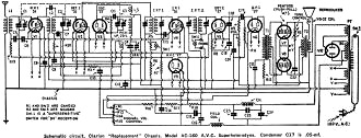
Schematic circuit, Clarion "Replacement" Chassis, Model AC-160 A.V.C. Superheterodyne.
Condenser C17 is 0.05-mf.
Posted June 21, 2022
(updated from original post on
9/15/2015)
Radio Service Data Sheets
These schematics, tuning instructions, and other data are reproduced from my
collection of vintage radio and electronics magazines. As back in the era, similar
schematic and service info was available for purchase from sources such as
SAMS Photofacts, but these printings
were a no-cost bonus for readers. There are 227 Radio Service Data Sheets as of
December 28, 2020.
-
AMRAD
Model 81 "Bel Canto"
-
GE
Model 250 Radio Service Data Sheet
- Hoffman
Model A300
- Emerson
Model 505
- Olympic
Models 6-501, 6-502, 6-503
- Radiola
Models 61-5, 61-10
- Farnsworth
Models ET-060, ET-061, ET-063
- General
Electric Model 321
-
Garod Model 6AU-1
- Truetone
Model D4620
- Westinghouse
Model H-148
- Wards Models
54BR-1501A, 1502A
- Majestic
Models 8S452, 8S473
- RCA Models
Q22A, Q32
- Zenith Model
5G003ZZ
- Mantola Models
92503 and 92504
- Emerson Model
508 Series 8-7434351 and Up
- Belmont Model
A-5D118
- Wards Model
74BR-2707A
- Crosley Model
56TP-L
- Admiral Model
7C60 Chassis 6B1
- 336
Belmont Radio Model 6D111, Series A
-
333 General Electric Models 100, 101, 103 and 105
- RCA Victor
Models 54B1, 54B-N, 54B2, 54B3 Radio Data Sheet 335
-
National Union "Presentation" Radio Model G-619
-
Zenith Radio Models 8H032, 8H033, 8H050, 8H052, 8H061
-
General Electric Farm Radio Model 280
-
Admiral Model 6RT44-7B1
-
Montgomery Ward Airline Model 04BR-1105A Radio
- Belmont
Model 678 Auto-Radio Set
- Sentinel
Model 217-P Portable Radio Set Radio
- Remler
Model No. 36 Dual-Wave Auto-Radio
-
Stromberg-Carlson No. 82 All-Wave Receiver
-
Majestic A.V.C. Model 290 Chassis
- FADA 9 Tube
Model 190 "Metal" All-Wave
- RCA Victor
Models 9T and K2 9-Tube, 5- to 566-Meter
-
Motorola "Golden Voice" Model
-
RCA Victor Model H-6
-
Simplex Model TA
-
Automatic "Magic Eye" Model A1
- Silvertone
Models 4488 and 4588 (Chassis No.101412) and 4488A and 4588A (Chassis No. 101412A)
- RCA Victor
Model M109 "De Luxe" 7-Tube Auto-Radio Receiver
- Crosley Model
6625 6-Tube 3-Band Receiver
- International
Model 77 Series 7-Tube Dual-Band Receiver
- Belmont
Model 6D121
-
General Electric Models 60, 62
- Admiral
Model 7C64
-
Radiola "28" Super and "104" Power Speaker
- Sonora
Model TW-49
-
Stromberg-Carlson Models 1020, 1120, Series 10
- Air King
Model 4604D
- Sparton Models
526, 526X, 526PS
- Truetone
Model D2624
- Admiral
Models 6EI, 6EIN
- Detrola Models
571A, 571B
-
General Electric Model 250
- Howard Model
920
- Colonial
Model 652 5-Tube Broadcast-Short-Wave
-
Fairbanks-Morse
9-Tube All-Wave Model 91
-
International Model 500 5-Tube Dual-Range Battery
- Emerson Model
678 "Auto-Dynamic" 5 Tube
-
Stromberg-Carlson
Nos. 230 and 231 Series
- Atwater
Kent Model 649 All-Wave
-
Howard Model G-26, and "Airplane 4" Model AA25
-
Montgomery Ward "Airline" Series 7GM 7-Tube High-Fidelity Receiver
- RCA
Victor Model T5-2 5-Tube, 2-Band A.C. Superheterodyne Receiver
-
Majestic
"Models 50," "51" and "52"
-
Bremer-Tully Model 7-70 and 7-71
-
General
Electric Model M-49 4-Tube Radio-Phonograph Dual-Wave Superheterodyne
- RCA-Victor
Radiola "Superette" Model R7 Superheterodyne
- Crosley Model AC-7
and AC-7C
-
Westinghouse
"Columnaire" Models WR-8 and WR-8-R (Remote Control)
-
Characteristics
of Metal Tubes - and Other "Octal" (8-Prong) Base Types
- Kolster K20,
K22, K25, K27 and K37 Six-Tube Receivers
-
Stromberg-Carlson
Nos. 62 and 63, 8-Tube High-Fidelity Chassis
- RCA Model
103, 4-Tube A.C. Compact Dual-Wave
- FADA "Special"
Model 265-A and FADA "7" Model 475-A
-
General Electric Model C-62 6-Tube Battery
- Emerson
5A Automotive
- Zenith
666 Automotive
- Motorola
100 Automotive
-
Crosley
Roamio 4-A-1 Automotive
-
American-Bosch
524A Automotive
- Crosley
Model 1316 (in Model 167 Console)
- RCA Victor
"High-Fidelity Electrola," Model R-99
- AMRAD
Model 81 ("Bel Canto" Series) Receiver
-
Fada 103 Fadalette, Stewart-Warner Series 108, DeWald 54 Dynette Sets
- RCA
Victor R-27 and Philco 53 Ultra-Midget A.C.-D.C. Radio Receivers
-
Majestic Models Fairfax and Sheffield 8-Tube
- Stromberg-Carlson
No. 29, 9-Tube Superhet
-
International Kadette Model 400 4-Tube Battery-Operated Superhet
- RCA Victor
Model 5M 5-Tube Auto Superhet
-
Majestic Model 11 Short-Wave Converter
-
Silver-Marshall
Model 727-DC Battery-Operated Superheterodyne
- RCA
Victor Model VHR-307 Home Recording - Phono-Radio Combination
-
Delco 32-Volt Radio Receiver Chassis Models RA-3, RB-3 and RC-3
- Majestic
Chassis Models 380 A.C. T.R.F., and 400 A.C.-D.C. Superheterodyne
- General
Motors S1A, S1B
- Admiral
Model 7C63, Chassis 7C1
- Westinghouse
Model H-133
- Arvin
Models 150TC, 151TC
- Kadette Model
90 Duplex
-
RCA-Victor "Magic Brain" Model 281
- Grunow
11A Chassis 11-Tube All-Wave Superheterodyne
-
Sears, Roebuck & Co., Silvertone "Rocket" Models 6110 and 6111
-
General Electric Model GD-52
-
Zenith Models 6D302, 6D311, 6D326, 6D336, 6D360
-
Allied Radio, Knight Model E10913
- Arvin Model
140P
- Emerson
Models 501, 502, 504
- Crosley
Model 56TD-W
- Hoffman
Model A500
-
Stewart-Warner
Model 9003-B
-
Zenith Models 6D014, 6D029
- Coronet
Model C-2
- Sparton
Models 7-46, 7-46PA, 8-46, 8-46PA
-
Stewart-Warner Models 9001-C, D, E, F
-
Zenith Models 5D011-5D027
- Bendix Models
636A, C, D
- ECA Model 108
-
International Model 66 and 666, 6-Tube Superhet
-
Ford-Philco
Radio, Model FT9, 6-Tube Auto-Radio Receiver
- Howard
Explorer Model W Deluxe 19 Tube All-Wave Superhet
- RCA Victor
Portable Table Electrola Model R-95
- Atwater
Kent Model 305Z 5-Tube 32 V. D.C. Superhet
- Kadette
Jewel Model 40 Chassis 3-Tube Ultra-Midget Receivers
-
General Electric Model N-60 6-Tube Auto Superheterodyne
-
Sparton Model 40 6-Tube T.R.F. Automotive Receiver
-
Clarion "Replacement" Chassis, Model AC-160 A.V.C. Superheterodyne
- Emerson Models
20A and 25A
- General
Electric K-40A
- Pilot Model
B-2
- RCA-Victor
Radiola Model M-30 Automotive Radio
- Motovox
Models 10A All-Electric and 10E Battery-Operated "Moto-Tetradynes"
-
Kennedy Superheterodyne Short-Wave Converter
- RCA
Victor Model R-78 B1-Acoustic 12-Tube
- Philco
Model 15 Series, 11-Tube Superheterodyne Chassis
-
Zenith Challenger Model 740
-
Sparton
Selectronne Receivers Models 1068 and 1068X
- Fada Model
155 Super Fadalette A.C.-D.C. Set
-
Clarion De Luxe Models AC-280 and 25-280
-
Crosley Model A-157 (River Roamio) Auto Radio
- Philco Model
'37-116 Codes 121 (Shadometer) and 122 (Dial Tuning)
-
Arvin Model 28
-
Philco Model 818
-
Fada Model 266 Motoset
-
Bosch Models 736, 737, 738
- RCA-Victor
Model 15U, Radio-Phonograph
- Sparton
Models 566 ("Bluebird" Mirror), A.C.-D.C. 5-Tube 2-Band Midget Superhet
- Atwater
Kent Model 776 6-Tube Auto Radio
- Stromberg-Carlson
No. 61 4-Band 7-Tube A.C.-D.C. Receiver
- Arvin Model
182TFM
- Crosley
Model 58TK
- Westinghouse
Model H-165
-
General Electric Models G-105 and G-106
- Silvertone
"F," "FF," "G," "H," and "J"
-
Stewart-Warner Model 03-5A1 to 03-5A9 (Chassis 03-5A) Senior Varsity Radio
- Radiola Models
61-6, 61-7
-
Westinghouse
Models H-104, H-105, H-107, H-108
- Farnsworth
Models EC-260, EK-262, EK-263, EK-264, EK-265
-
United
Models 980744, 980745
-
Stewart-Warner (R-127 Chassis) Models 1271 to 1279 All-Wave
- ERLA Model
4500 Dual-Wave T.R.F. 4-Tube A.C. Receiver
- Clarion No. TC-31
5-Tube A.C.-D.C. Superhet.
- Detrola Model
105C 5-Tube Dual-Band A.C.-D.C.
- Zenith
6-Tube All-Wave Chassis No. 5634
- RCA Victor
Model 261, 555 to 107 Meter
- Philco
Model 38-116; Code 125
-
Stewart-Warner "Ferrodyne" Chassis Model R-136
-
American-Bosch
Model 43OT 5-Tube 3-Band Superheterodyne
- RCA
Victor Model C9-4 9-Tube 3-Band Superheterodyne
- Kennedy "Model
826B" Combination Receiver
- Steinite
50-A and 102-A
- Pilot Model
63 All-Wave 6-Tube Superheterodyne
- Stromberg-Carlson
No. 69 4-Tube All-Wave Superhet. Selector (Converter)
- RCA
Victor Model 102 4-Tube A.C.-D.C. T.R.F. Receiver
- Bosch Models 60
and 61
-
Atwater Kent Models 30, 33, 35, 48 and 49
- Crosley Model
120 Senior Superheterodyne (Pliodynatron) Chassis
-
Columbia Screen-Grid 8 Receiver
-
General Electric Models A82 and A87, 8-Metal-Tube All-Wave A.C. Superhet.
- Colonial
31 and 32 D.C.
- Zenith 5-Tube
Triple-Wave Chassis nos. 5508 and 5509
- Remler Model
46 ("Scottie")
- General
Electric FA-60 and FA-61
-
Stewart-Warner
Series 900
-
Howard
Model B-5 (715), Series 1 and 2 (Sheaffer Radio-Clock-Pen Desk Set)
-
Ford-Philco Car-Radio Models F-1440 and F-1442
-
Brunswick Model 31 Combination Radio and Panatrope
- Emerson Models
38, 42 and 49, 6-Tube Dual-Wave (Chassis U6)
-
General Motors Chevrolet No. 601574 Automotive
-
RCA Victor M-104 (and M-108) Automotive
- Arvin-Ford
17-A Automotive
-
Westinghouse Model WR 207 & WR 208 5-Tube Dual-Band Superheterodyne
- Radiolas
"Super VIII" (AR-810, "Semi-Portable" (AR-812), 24 and 26
- Howard Model
45 A. V. C.
- Majestic
Model 25
-
Galvin Motorola Model 61
-
Arvin Model 6
- Admiral
Models 7T06, 7T12
- Garod Model 5A1
- Hoffman Model A301
-
Knight Model E10716 Battery Portable
- Arvin Models 555,
555A, 552N, 552AN
- Grantline Models
605, 606
- Truetone Model
D2616
- Belmont Model
5D128
- Arvin Models 444,
444A
-
International Kadette Model 1019
-
Stewart-Warner Models 97-561 to 97-569
- General
Electric Model 280
- Zenith Models 5R080,
5R086
- Truetone Models
D1747, D1748
-
Crosley Roamio Automotive T.R.F. Models 90, 91, 92
-
Crosley Roamio Automotive Superheterodyne Models 95, 96
-
Wells-Gardner Series 062
-
Emerson
Model AZ-196
- Belmont Model
5P19
- Crosley
Fortyfive
- Crosley Model
56FC
-
Emerson
Models 507, 509, 518, 522, 535
- Garod Model 6AU-1
- General
Electric Models 219, 202, 221
-
Crosley "Chairside" Model 567
-
Belmont Model 408 Battery "Farm"
- Wards Model
74BR-1055A
- Farnsworth
Models EK-081, EK-082, EK-083, EK-681
- Philco
Model 200-X Radio
-
Admiral "Aeroscope" Models 161-5L, 162-5L and 163-5L
- Philco
Model 59, 4-Tube A.C. Midget Superheterodyne
- Zenith
Farm Model 6V 27, 6-Tube Superhet
- Ward 10-Tube
All-Wave High-Fidelity Superhet, Series ODM
-
Philco-Packard
Deluxe
-
Canadian
Westinghouse Model 175
- Crosley Model
1155
- Philco Models
39 and 39A
-
Arvin Model 35 8-Tube Car-Radio
- Hetro
Air-Ace Series M
- Westinghouse
Models H-161, H-168, H-168A
- Garod Model 5A4
- Arvin Models 152T,
153T
- Belmont Model 5240
- Mantola Models 92505,
92506
- General Electric
Models 102, 102W, 107, 107W, 114, 114W, 115, 115W
- Crosley Model
555 (A.F.M.)
- Crosley Model
515 (Fiver)
- Crosley Model
425 (Travo)
-
Firestone-Stewart-Warner Model R1332
- Fairbanks-Morse
Model 81 "Farm" Set
- Clarion Model
423, 470, 471, 472, 480
-
International Radio Corp. Model 90
- Belmont Model
578 Series A
|


