|
July 1932 Radio-Craft
 [Table
of Contents] [Table
of Contents]
Wax nostalgic about and learn from the history of early electronics.
See articles from Radio-Craft,
published 1929 - 1953. All copyrights are hereby acknowledged.
|
This Radio Service Data Sheet for
the Sparton Model 40 6-Tube T.R.F. Automotive Receiver is an example of the dozens
of similar schematic and alignment instruction sheets that have been posted on RF
Cafe over the years. They appeared in electronics industry magazines of the era
- Radio-Craft in this instance. Obtaining technical information on most things, even readily
available items, prior to the Internet era was often very difficult - if not impossible.
Service centers had what was need provided by manufacturers and distributors, but
if you wanted to find a part number or service data on a refrigerator, radio, lawn
mower, garage door opener, etc., and did not have the original paperwork, you were
usually out of luck. Nowadays a Web search will quite often get you what you need
thanks to people (like me) who go to the trouble
of making the information available.
Sparton Model 40 6-Tube T.R.F. Automotive Receiver Radio Service
Data Sheet
Lafoy-type Automatic Volume Control; Remote Tuning Control; Electro-Dynamic
Reproducer
To maintain constant signal output, regardless of the intensity of the incoming
signal (within practical limits), to overcome the reduction in signal intensity
which will occur in a given locality (due to metallic structures, ore deposits,
etc.) it is necessary to incorporate some form of volume control which will operate
to vary the gain in the amplification of the receiver in proportion to the loss
in carrier signal strength. Most automatic volume controls or A.V.C. circuits operate
to vary the control-grid of the amplifier tubes, in accordance with the A.F. modulation
of the station's carrier; the "Lafoy" system, however, varies the control-grid bias
more nearly in accord with the intensity variations of the station's carrier itself,
the A.V.C., tube V6 in the diagram, functioning more nearly as an R.F. amplifier
than as a detector.
High amplification in this set is obtained through the use of a three-stage R.F.
amplifier incorporating screen-grid tubes of the "automotive" type, the output of
this section feeding a screen-grid detector. The audio circuit comprises a single
pentode, which is impedance- and resistance-capacity-coupled to the detector.
The values of the components are as follows: Condensers C1 C2, C3, C4, tuning
units; C5, antenna compensator; C6, C8, C10, C12, 0.2-mf.; C7A 0.3-mf.; B, 0.2-mf.
C, 0.3-mf.; C9A, 0.3-mf., B, 0.2-mf., C, 0.3-mf.; C11A, 0.3-mf., C, 0.3-mf.; C13,
C14, 0.00025-mf.; C15A, 0.3-mf., n, 0.2-mf.; C16, coupling condenser, 0.01-mf.;
C17, 0.0005-mf.; C18, 0.006-mf.; C19, 1.0 mf.; C20, 0.1-mf.
Resistors R1, R2, R5, R7, 20,000 ohms; R3, R4, R6, 5,000 ohms; R8, 30,000 ohms;
R9, manual volume control, 1/4-meg.; R10, 1/4-meg.; R11, 160 ohms; R12, 350 ohms.
Correct methods for installing and servicing antennas and interference suppressors
have been described in past issues of Radio-Craft. However, a little additional
data is available.
 For the aerial in collapsible type tops,
we recommend that the "false top" type be employed. This type of aerial is constructed
in the following manner: For the aerial in collapsible type tops,
we recommend that the "false top" type be employed. This type of aerial is constructed
in the following manner:
Fashion two pieces of drill cloth that are the same color as the top material,
as long as, and approximately six inches narrower than the roof. On one section,
lay a piece of light weight felt of the same dimensions, and then lay on top of
the felt a piece of 16-mesh copper screen wire the same size. On top of this wire,
lay another piece of light weight felt and over this the second section of drill
cloth, then sew the edges of the combination together.
The top deck is removed from the roof bows and the aerial is placed on top of
thorn. The top decking is then placed back over the aerial.
where it is desired to let the top down, it is advisable to connect the aerial
lead-in wire to the aerial at the rear, and let the shielding on this wire, extend
only for a distance of about three feet from the receiver end. In such cases, the
lead-in wire is run through the floor boards back of the seat underneath the car,
up to the receiver.
Note that in this receiver there are two fuses; one of them is of 1/8-A. rating,
and is connected in the "B" battery jumper wire, while the other is a 5 A unit located
in the receiving unit near tile ground binding post.
Interference may be distinguished by the sound: Generator noises (eliminated
by bypassing the commutator) are tone frequencies quite different from the staccato
tapping sound of high-tension spark interference ; high-tension interference is
a sharp, raspy sound and can be eliminated practically 100 percent by means of spark
suppressors (on the distributor and spark plugs); low-tension breaker point noise
is not readily distinguished from high-tension interference, but will be the sound
remaining after spark suppressors have been installed. Low-tension breaker interference
is difficult to eliminate. Try reversing the two primary leads to the coil; install
a bypass condenser connected from the engine to the ammeter and switch lead.
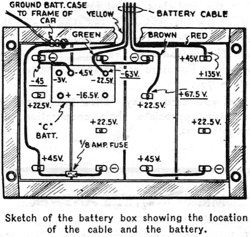
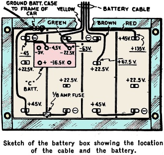
Sketch of the battery box showing the location of the cable and the battery.
The operating voltage and current characteristics of this set are to be measured
with a set analyzer equipped with a voltmeter of the 1,000-ohms-per-volt type; the
manual volume control must be turned to the full on position, and with no signal
reception.
The filament potential of all tubes is 6 volts. Plate potential, V1, V2, V3,
V5, 135 volts; V4, 132 volts ; V6, zero. Control-grid, V1, v2, V3, 1.5 volts; V4,
10 volts; V5, V6, 18 volts. Screen-grid potential,V1, V2, V3, V4, 67.5 volts; V5,
135 volts; V6, zero. Plate current, V1, V2, V3, 3 ma.; V4, 0.1-ma.; V5, 8 ma.; V6,
zero.
The antenna compensating condenser C5 is to be adjusted at the time the receiver
is installed. Tune in a weak station between 1200 and 1400 kc., turn the volume
control full on, and then, using an insulated screwdriver, adjust C5 for maximum
receiver output. Never adjust either the C5, or the remaining trimmers, with the
cover removed.
Circuit oscillation can be caused either by tubes or the receiver itself. Check
the contact surfaces between the partitions and the rotor shaft, making sure that
a good ground is obtained. Do not under any conditions oil the shaft under the contacts.
Make sure that the receiver chassis is well grounded.
For best results it is essential that the receiver unit be located so that the
remote control flexible-shaft runs direct (that is, without sharp bends).
The battery circuit for this receiver is unusual, as indicated in the diagram;
an additional figure illustrates the connections.
The "A" battery consumption of this set is about 2 1/2 A.; the "B" requirements,
about 20 ma.
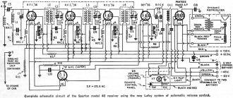
Complete schematic circuit of the Spartan model 40 receiver using the new Lafoy
system of automatic volume control.
Posted August 4, 2023
(updated from original post
on 9/15/2015)
Radio Service Data Sheets
These schematics, tuning instructions, and other data are reproduced from my
collection of vintage radio and electronics magazines. As back in the era, similar
schematic and service info was available for purchase from sources such as
SAMS Photofacts, but these printings
were a no-cost bonus for readers. There are 227 Radio Service Data Sheets as of
December 28, 2020.
-
AMRAD
Model 81 "Bel Canto"
-
GE
Model 250 Radio Service Data Sheet
- Hoffman
Model A300
- Emerson
Model 505
- Olympic
Models 6-501, 6-502, 6-503
- Radiola
Models 61-5, 61-10
- Farnsworth
Models ET-060, ET-061, ET-063
- General
Electric Model 321
-
Garod Model 6AU-1
- Truetone
Model D4620
- Westinghouse
Model H-148
- Wards Models
54BR-1501A, 1502A
- Majestic
Models 8S452, 8S473
- RCA Models
Q22A, Q32
- Zenith Model
5G003ZZ
- Mantola Models
92503 and 92504
- Emerson Model
508 Series 8-7434351 and Up
- Belmont Model
A-5D118
- Wards Model
74BR-2707A
- Crosley Model
56TP-L
- Admiral Model
7C60 Chassis 6B1
- 336
Belmont Radio Model 6D111, Series A
-
333 General Electric Models 100, 101, 103 and 105
- RCA Victor
Models 54B1, 54B-N, 54B2, 54B3 Radio Data Sheet 335
-
National Union "Presentation" Radio Model G-619
-
Zenith Radio Models 8H032, 8H033, 8H050, 8H052, 8H061
-
General Electric Farm Radio Model 280
-
Admiral Model 6RT44-7B1
-
Montgomery Ward Airline Model 04BR-1105A Radio
- Belmont
Model 678 Auto-Radio Set
- Sentinel
Model 217-P Portable Radio Set Radio
- Remler
Model No. 36 Dual-Wave Auto-Radio
-
Stromberg-Carlson No. 82 All-Wave Receiver
-
Majestic A.V.C. Model 290 Chassis
- FADA 9 Tube
Model 190 "Metal" All-Wave
- RCA Victor
Models 9T and K2 9-Tube, 5- to 566-Meter
-
Motorola "Golden Voice" Model
-
RCA Victor Model H-6
-
Simplex Model TA
-
Automatic "Magic Eye" Model A1
- Silvertone
Models 4488 and 4588 (Chassis No.101412) and 4488A and 4588A (Chassis No. 101412A)
- RCA Victor
Model M109 "De Luxe" 7-Tube Auto-Radio Receiver
- Crosley Model
6625 6-Tube 3-Band Receiver
- International
Model 77 Series 7-Tube Dual-Band Receiver
- Belmont
Model 6D121
-
General Electric Models 60, 62
- Admiral
Model 7C64
-
Radiola "28" Super and "104" Power Speaker
- Sonora
Model TW-49
-
Stromberg-Carlson Models 1020, 1120, Series 10
- Air King
Model 4604D
- Sparton Models
526, 526X, 526PS
- Truetone
Model D2624
- Admiral
Models 6EI, 6EIN
- Detrola Models
571A, 571B
-
General Electric Model 250
- Howard Model
920
- Colonial
Model 652 5-Tube Broadcast-Short-Wave
-
Fairbanks-Morse
9-Tube All-Wave Model 91
-
International Model 500 5-Tube Dual-Range Battery
- Emerson Model
678 "Auto-Dynamic" 5 Tube
-
Stromberg-Carlson
Nos. 230 and 231 Series
- Atwater
Kent Model 649 All-Wave
-
Howard Model G-26, and "Airplane 4" Model AA25
-
Montgomery Ward "Airline" Series 7GM 7-Tube High-Fidelity Receiver
- RCA
Victor Model T5-2 5-Tube, 2-Band A.C. Superheterodyne Receiver
-
Majestic
"Models 50," "51" and "52"
-
Bremer-Tully Model 7-70 and 7-71
-
General
Electric Model M-49 4-Tube Radio-Phonograph Dual-Wave Superheterodyne
- RCA-Victor
Radiola "Superette" Model R7 Superheterodyne
- Crosley Model AC-7
and AC-7C
-
Westinghouse
"Columnaire" Models WR-8 and WR-8-R (Remote Control)
-
Characteristics
of Metal Tubes - and Other "Octal" (8-Prong) Base Types
- Kolster K20,
K22, K25, K27 and K37 Six-Tube Receivers
-
Stromberg-Carlson
Nos. 62 and 63, 8-Tube High-Fidelity Chassis
- RCA Model
103, 4-Tube A.C. Compact Dual-Wave
- FADA "Special"
Model 265-A and FADA "7" Model 475-A
-
General Electric Model C-62 6-Tube Battery
- Emerson
5A Automotive
- Zenith
666 Automotive
- Motorola
100 Automotive
-
Crosley
Roamio 4-A-1 Automotive
-
American-Bosch
524A Automotive
- Crosley
Model 1316 (in Model 167 Console)
- RCA Victor
"High-Fidelity Electrola," Model R-99
- AMRAD
Model 81 ("Bel Canto" Series) Receiver
-
Fada 103 Fadalette, Stewart-Warner Series 108, DeWald 54 Dynette Sets
- RCA
Victor R-27 and Philco 53 Ultra-Midget A.C.-D.C. Radio Receivers
-
Majestic Models Fairfax and Sheffield 8-Tube
- Stromberg-Carlson
No. 29, 9-Tube Superhet
-
International Kadette Model 400 4-Tube Battery-Operated Superhet
- RCA Victor
Model 5M 5-Tube Auto Superhet
-
Majestic Model 11 Short-Wave Converter
-
Silver-Marshall
Model 727-DC Battery-Operated Superheterodyne
- RCA
Victor Model VHR-307 Home Recording - Phono-Radio Combination
-
Delco 32-Volt Radio Receiver Chassis Models RA-3, RB-3 and RC-3
- Majestic
Chassis Models 380 A.C. T.R.F., and 400 A.C.-D.C. Superheterodyne
- General
Motors S1A, S1B
- Admiral
Model 7C63, Chassis 7C1
- Westinghouse
Model H-133
- Arvin
Models 150TC, 151TC
- Kadette Model
90 Duplex
-
RCA-Victor "Magic Brain" Model 281
- Grunow
11A Chassis 11-Tube All-Wave Superheterodyne
-
Sears, Roebuck & Co., Silvertone "Rocket" Models 6110 and 6111
-
General Electric Model GD-52
-
Zenith Models 6D302, 6D311, 6D326, 6D336, 6D360
-
Allied Radio, Knight Model E10913
- Arvin Model
140P
- Emerson
Models 501, 502, 504
- Crosley
Model 56TD-W
- Hoffman
Model A500
-
Stewart-Warner
Model 9003-B
-
Zenith Models 6D014, 6D029
- Coronet
Model C-2
- Sparton
Models 7-46, 7-46PA, 8-46, 8-46PA
-
Stewart-Warner Models 9001-C, D, E, F
-
Zenith Models 5D011-5D027
- Bendix Models
636A, C, D
- ECA Model 108
-
International Model 66 and 666, 6-Tube Superhet
-
Ford-Philco
Radio, Model FT9, 6-Tube Auto-Radio Receiver
- Howard
Explorer Model W Deluxe 19 Tube All-Wave Superhet
- RCA Victor
Portable Table Electrola Model R-95
- Atwater
Kent Model 305Z 5-Tube 32 V. D.C. Superhet
- Kadette
Jewel Model 40 Chassis 3-Tube Ultra-Midget Receivers
-
General Electric Model N-60 6-Tube Auto Superheterodyne
-
Sparton Model 40 6-Tube T.R.F. Automotive Receiver
-
Clarion "Replacement" Chassis, Model AC-160 A.V.C. Superheterodyne
- Emerson Models
20A and 25A
- General
Electric K-40A
- Pilot Model
B-2
- RCA-Victor
Radiola Model M-30 Automotive Radio
- Motovox
Models 10A All-Electric and 10E Battery-Operated "Moto-Tetradynes"
-
Kennedy Superheterodyne Short-Wave Converter
- RCA
Victor Model R-78 B1-Acoustic 12-Tube
- Philco
Model 15 Series, 11-Tube Superheterodyne Chassis
-
Zenith Challenger Model 740
-
Sparton
Selectronne Receivers Models 1068 and 1068X
- Fada Model
155 Super Fadalette A.C.-D.C. Set
-
Clarion De Luxe Models AC-280 and 25-280
-
Crosley Model A-157 (River Roamio) Auto Radio
- Philco Model
'37-116 Codes 121 (Shadometer) and 122 (Dial Tuning)
-
Arvin Model 28
-
Philco Model 818
-
Fada Model 266 Motoset
-
Bosch Models 736, 737, 738
- RCA-Victor
Model 15U, Radio-Phonograph
- Sparton
Models 566 ("Bluebird" Mirror), A.C.-D.C. 5-Tube 2-Band Midget Superhet
- Atwater
Kent Model 776 6-Tube Auto Radio
- Stromberg-Carlson
No. 61 4-Band 7-Tube A.C.-D.C. Receiver
- Arvin Model
182TFM
- Crosley
Model 58TK
- Westinghouse
Model H-165
-
General Electric Models G-105 and G-106
- Silvertone
"F," "FF," "G," "H," and "J"
-
Stewart-Warner Model 03-5A1 to 03-5A9 (Chassis 03-5A) Senior Varsity Radio
- Radiola Models
61-6, 61-7
-
Westinghouse
Models H-104, H-105, H-107, H-108
- Farnsworth
Models EC-260, EK-262, EK-263, EK-264, EK-265
-
United
Models 980744, 980745
-
Stewart-Warner (R-127 Chassis) Models 1271 to 1279 All-Wave
- ERLA Model
4500 Dual-Wave T.R.F. 4-Tube A.C. Receiver
- Clarion No. TC-31
5-Tube A.C.-D.C. Superhet.
- Detrola Model
105C 5-Tube Dual-Band A.C.-D.C.
- Zenith
6-Tube All-Wave Chassis No. 5634
- RCA Victor
Model 261, 555 to 107 Meter
- Philco
Model 38-116; Code 125
-
Stewart-Warner "Ferrodyne" Chassis Model R-136
-
American-Bosch
Model 43OT 5-Tube 3-Band Superheterodyne
- RCA
Victor Model C9-4 9-Tube 3-Band Superheterodyne
- Kennedy "Model
826B" Combination Receiver
- Steinite
50-A and 102-A
- Pilot Model
63 All-Wave 6-Tube Superheterodyne
- Stromberg-Carlson
No. 69 4-Tube All-Wave Superhet. Selector (Converter)
- RCA
Victor Model 102 4-Tube A.C.-D.C. T.R.F. Receiver
- Bosch Models 60
and 61
-
Atwater Kent Models 30, 33, 35, 48 and 49
- Crosley Model
120 Senior Superheterodyne (Pliodynatron) Chassis
-
Columbia Screen-Grid 8 Receiver
-
General Electric Models A82 and A87, 8-Metal-Tube All-Wave A.C. Superhet.
- Colonial
31 and 32 D.C.
- Zenith 5-Tube
Triple-Wave Chassis nos. 5508 and 5509
- Remler Model
46 ("Scottie")
- General
Electric FA-60 and FA-61
-
Stewart-Warner
Series 900
-
Howard
Model B-5 (715), Series 1 and 2 (Sheaffer Radio-Clock-Pen Desk Set)
-
Ford-Philco Car-Radio Models F-1440 and F-1442
-
Brunswick Model 31 Combination Radio and Panatrope
- Emerson Models
38, 42 and 49, 6-Tube Dual-Wave (Chassis U6)
-
General Motors Chevrolet No. 601574 Automotive
-
RCA Victor M-104 (and M-108) Automotive
- Arvin-Ford
17-A Automotive
-
Westinghouse Model WR 207 & WR 208 5-Tube Dual-Band Superheterodyne
- Radiolas
"Super VIII" (AR-810, "Semi-Portable" (AR-812), 24 and 26
- Howard Model
45 A. V. C.
- Majestic
Model 25
-
Galvin Motorola Model 61
-
Arvin Model 6
- Admiral
Models 7T06, 7T12
- Garod Model 5A1
- Hoffman Model A301
-
Knight Model E10716 Battery Portable
- Arvin Models 555,
555A, 552N, 552AN
- Grantline Models
605, 606
- Truetone Model
D2616
- Belmont Model
5D128
- Arvin Models 444,
444A
-
International Kadette Model 1019
-
Stewart-Warner Models 97-561 to 97-569
- General
Electric Model 280
- Zenith Models 5R080,
5R086
- Truetone Models
D1747, D1748
-
Crosley Roamio Automotive T.R.F. Models 90, 91, 92
-
Crosley Roamio Automotive Superheterodyne Models 95, 96
-
Wells-Gardner Series 062
-
Emerson
Model AZ-196
- Belmont Model
5P19
- Crosley
Fortyfive
- Crosley Model
56FC
-
Emerson
Models 507, 509, 518, 522, 535
- Garod Model 6AU-1
- General
Electric Models 219, 202, 221
-
Crosley "Chairside" Model 567
-
Belmont Model 408 Battery "Farm"
- Wards Model
74BR-1055A
- Farnsworth
Models EK-081, EK-082, EK-083, EK-681
- Philco
Model 200-X Radio
-
Admiral "Aeroscope" Models 161-5L, 162-5L and 163-5L
- Philco
Model 59, 4-Tube A.C. Midget Superheterodyne
- Zenith
Farm Model 6V 27, 6-Tube Superhet
- Ward 10-Tube
All-Wave High-Fidelity Superhet, Series ODM
-
Philco-Packard
Deluxe
-
Canadian
Westinghouse Model 175
- Crosley Model
1155
- Philco Models
39 and 39A
-
Arvin Model 35 8-Tube Car-Radio
- Hetro
Air-Ace Series M
- Westinghouse
Models H-161, H-168, H-168A
- Garod Model 5A4
- Arvin Models 152T,
153T
- Belmont Model 5240
- Mantola Models 92505,
92506
- General Electric
Models 102, 102W, 107, 107W, 114, 114W, 115, 115W
- Crosley Model
555 (A.F.M.)
- Crosley Model
515 (Fiver)
- Crosley Model
425 (Travo)
-
Firestone-Stewart-Warner Model R1332
- Fairbanks-Morse
Model 81 "Farm" Set
- Clarion Model
423, 470, 471, 472, 480
-
International Radio Corp. Model 90
- Belmont Model
578 Series A
|