|
June 1936 Radio-Craft
 [Table of Contents] [Table of Contents]
Wax nostalgic about and learn from the history of early electronics.
See articles from Radio-Craft,
published 1929 - 1953. All copyrights are hereby acknowledged.
|
These 8 new schematics from a 1936
issue of Radio-Craft magazine for vintage tube-type car radios brings the
total to 210 posted on RF Cafe. Included are Motorola "Golden Voice" Model, RCA
Victor Model H-6, Simplex Model TA, Automatic "Magic Eye" Model A1, Arvin Model
28, Philco Model 818, Fada Model 266 Motoset, Bosch Models 736, 737, 738. The Motorla
"golden Voice" model features a "magic eliminode" circuit which not only filters
out automobile engine noise, but balances the noise out of the antenna lead, so
that suppressorless operation is possible on almost all cars. A glance at the schematic
shows that all that magic is performed by a built-in L-C filter network for the
power supply, and an antenna tuning circuit. In those days, installation of a radio
in a car usually required the skills of an electronics technician in order to match
the antenna and fine-tune the receiver according to its environment.
Diagrams of the Newest Car-Radio Receivers
The friend of design of the new receivers can most readily by an examination
of the actual circuits.
 (1) Automatic "Magic Eye" Model
A1. A novelty of this set is its "magic eye" 6E5 tuning tube. The set may
be had with or without this feature. Operation is possible in most cases with only
a generator condenser and a distributor suppressor. The set is mounted directly
below the dash, and no remote control is used. Alignment of the set is done at 1,400
kc. Installation is made with 2 screws fastened to the dash and a single heavy bolt
at the rear, through the motor compartment bulkhead. For installation in the Willys
77, a roof antenna of about 10 square ft. of copper screen should be used. Voltages:
Plate - V1, V2, 220; V3, 120; V4, 200. S.-G. - V1, V2, 95; V4, 220. Cath. - V1,
3; V2, 3.7; V3, 1.3. Bias of V4, 14 V., drop across the "B" choke. (Photo on page.
712) (1) Automatic "Magic Eye" Model
A1. A novelty of this set is its "magic eye" 6E5 tuning tube. The set may
be had with or without this feature. Operation is possible in most cases with only
a generator condenser and a distributor suppressor. The set is mounted directly
below the dash, and no remote control is used. Alignment of the set is done at 1,400
kc. Installation is made with 2 screws fastened to the dash and a single heavy bolt
at the rear, through the motor compartment bulkhead. For installation in the Willys
77, a roof antenna of about 10 square ft. of copper screen should be used. Voltages:
Plate - V1, V2, 220; V3, 120; V4, 200. S.-G. - V1, V2, 95; V4, 220. Cath. - V1,
3; V2, 3.7; V3, 1.3. Bias of V4, 14 V., drop across the "B" choke. (Photo on page.
712)
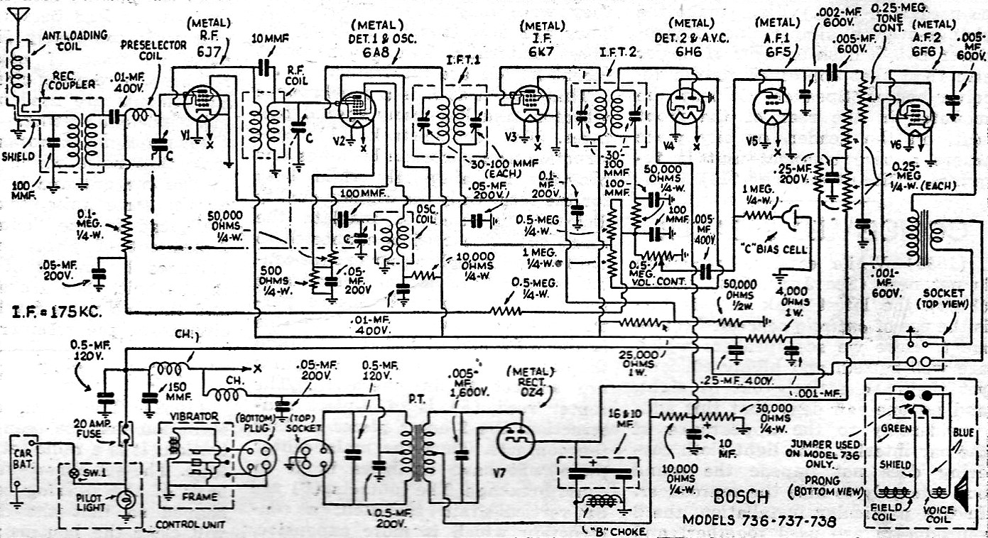
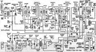 (2) Bosch Models 736, 737, 738.
These sets are the same except for the speaker equipment. The model 736 uses a self-contained
speaker, model, 737 is used with a header-type speaker, and 738 has a separately
mounted dash speaker. Various makes of cars will require different treatment for
noise suppression, but complete instructions are furnished with the set. The tubes
used in this set are quick-heater types. The tone control knob is located on the
side of the receiver case. The antenna cable is cut to a specific length and should
not be shortened. Any excess may be coiled up out of the way. An antenna loading
is included in this cable. This set may be used with any type of car antenna. The
new grid-bias cell is used in this receiver and under normal use will not need replacement
during the life of the car. The 0Z4 rectifier tube is similar in action to the old
BH rectifiers, but is much improved. Voltages to be found in this set will vary
rather widely according to the condition of the battery and vibrator, but the normal
high voltage is around 240 V. A 20 A. fuse is used forprotection of battery. (Photo
on page 712) (2) Bosch Models 736, 737, 738.
These sets are the same except for the speaker equipment. The model 736 uses a self-contained
speaker, model, 737 is used with a header-type speaker, and 738 has a separately
mounted dash speaker. Various makes of cars will require different treatment for
noise suppression, but complete instructions are furnished with the set. The tubes
used in this set are quick-heater types. The tone control knob is located on the
side of the receiver case. The antenna cable is cut to a specific length and should
not be shortened. Any excess may be coiled up out of the way. An antenna loading
is included in this cable. This set may be used with any type of car antenna. The
new grid-bias cell is used in this receiver and under normal use will not need replacement
during the life of the car. The 0Z4 rectifier tube is similar in action to the old
BH rectifiers, but is much improved. Voltages to be found in this set will vary
rather widely according to the condition of the battery and vibrator, but the normal
high voltage is around 240 V. A 20 A. fuse is used forprotection of battery. (Photo
on page 712)
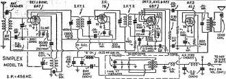 (3) Simplex Model TA. This
is one of comparatively few using the synchronous type of vibrator, which eliminates
the necessity for a rectifier tube. If the car battery is grounded on the negative
side, the vibrator must he removed from its socket and tuned half-way around before
inserting. It is normally shipped for use with the ground on the positive side.
An antenna trimmer is used to adjust the set to the most accurate balance with the,
particular antenna used. The trimmer is located at the bottom of the cabinet under
a small plug. It should be adjusted with. the set in the car, and connected to the
car antenna. Ordinarily, only a distributor suppressor is necessary with this car,
the battery input being well filtered. (3) Simplex Model TA. This
is one of comparatively few using the synchronous type of vibrator, which eliminates
the necessity for a rectifier tube. If the car battery is grounded on the negative
side, the vibrator must he removed from its socket and tuned half-way around before
inserting. It is normally shipped for use with the ground on the positive side.
An antenna trimmer is used to adjust the set to the most accurate balance with the,
particular antenna used. The trimmer is located at the bottom of the cabinet under
a small plug. It should be adjusted with. the set in the car, and connected to the
car antenna. Ordinarily, only a distributor suppressor is necessary with this car,
the battery input being well filtered.
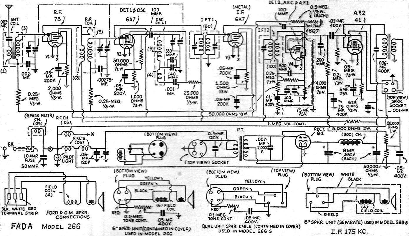
 (4) Fada Model 266 Motoset.
This set may be used with a self-contained speaker, a roof or other outside speaker,
or it may be used with dual speakers. The plug connections of the different types
are shown at the bottom of the diagram at right. The input "A" leads are very completely
filtered, to keep out ignition noise. The antenna input transformer is of the iron-core
type, and this unit raises the sensitivity of the set to a considerable degree.
Two of the new metal tubes are used, including the 6Q7 double-diode triode, which
is closely equivalent to the 75. Voltages at tube prongs are: Plate - V1, 162; V2,
160; V3, 162; V4, 107; V5, 226. S.-G. - V1, 68; V2, 66; V5, 236. Plate current:
V1, 3; V2, 3.4; V3, 2.9; V4, 0.3; V5, 19; V6, (total) 37. These readings were taken
with a 1,000 ohm-per-volt meter and are not indicative of effective voltages. The
readings were taken with a supply voltage, of 6.0, and the current was 5.6 A. The
I.F. transformers are to be aligned at 175 kc., while the gang trimmers are set
at a reading of 1,500 kc. The oscillator aeries trimmer must be aligned at a frequency
of 600 kc. The "hot A" lead has a fused connector for protection. (This is the circuit
of the receiver shown at upper right, page 713.) (4) Fada Model 266 Motoset.
This set may be used with a self-contained speaker, a roof or other outside speaker,
or it may be used with dual speakers. The plug connections of the different types
are shown at the bottom of the diagram at right. The input "A" leads are very completely
filtered, to keep out ignition noise. The antenna input transformer is of the iron-core
type, and this unit raises the sensitivity of the set to a considerable degree.
Two of the new metal tubes are used, including the 6Q7 double-diode triode, which
is closely equivalent to the 75. Voltages at tube prongs are: Plate - V1, 162; V2,
160; V3, 162; V4, 107; V5, 226. S.-G. - V1, 68; V2, 66; V5, 236. Plate current:
V1, 3; V2, 3.4; V3, 2.9; V4, 0.3; V5, 19; V6, (total) 37. These readings were taken
with a 1,000 ohm-per-volt meter and are not indicative of effective voltages. The
readings were taken with a supply voltage, of 6.0, and the current was 5.6 A. The
I.F. transformers are to be aligned at 175 kc., while the gang trimmers are set
at a reading of 1,500 kc. The oscillator aeries trimmer must be aligned at a frequency
of 600 kc. The "hot A" lead has a fused connector for protection. (This is the circuit
of the receiver shown at upper right, page 713.)
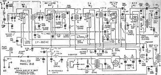 (5) Philco Model 818. When
this set is used in a car having a lop antenna, under-car antenna, spare-wheel antenna,
or any other having low relative capacity (50 mmf. to 450 mmf.), use connector plug
in "A." For antennas of high relative capacity, such as metal insert top antenna,
insulated door, insulated trunk cover (450 to 2,500 mmr.), use condenser plug in
"B." Adjustment frequencies are: 1,550 kc. and 580 kc., for R.F. and detector. The
antenna adjustment should preferably be made with the set in the car and attached
to the car antenna. Iron-core I.F. transformers are used and add greatly to the
sensitivity of the receiver. All leads out of the receiver case are very completely
filtered. Continuously variable tone compensation is available. The input lead from
battery is fused. The manufacturers prefer not to give complete voltage data, since
voltages vary widely with different conditions, but with a fully-charged battery,
the high voltage is about 180 to 220 V. (Photo on page 712.) (5) Philco Model 818. When
this set is used in a car having a lop antenna, under-car antenna, spare-wheel antenna,
or any other having low relative capacity (50 mmf. to 450 mmf.), use connector plug
in "A." For antennas of high relative capacity, such as metal insert top antenna,
insulated door, insulated trunk cover (450 to 2,500 mmr.), use condenser plug in
"B." Adjustment frequencies are: 1,550 kc. and 580 kc., for R.F. and detector. The
antenna adjustment should preferably be made with the set in the car and attached
to the car antenna. Iron-core I.F. transformers are used and add greatly to the
sensitivity of the receiver. All leads out of the receiver case are very completely
filtered. Continuously variable tone compensation is available. The input lead from
battery is fused. The manufacturers prefer not to give complete voltage data, since
voltages vary widely with different conditions, but with a fully-charged battery,
the high voltage is about 180 to 220 V. (Photo on page 712.)
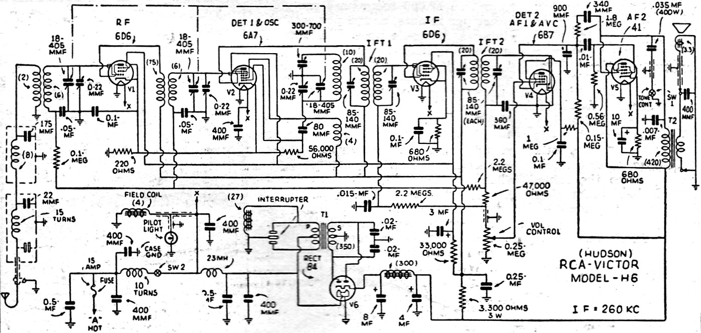
 6) RCA Victor Model H-6.
A special antenna circuit is used which contains a band-pass filter, affecting a
sharp reduction of frequencies out of the band of 540 to 1,660 kc. "Hot" spots of
ignition interference on the chassis have been carefully located and grounded. A
single-position tone control is used. There is a total of 7 tuned circuits in the
R.F. section of the set. The reproducer is a separate unit. Alignment frequencies
are: 1,400 kc. for ant. and det. coils, and 600 and 1,400 kc. for osc. coil. Undistorted
output is 1.75 W. and maximum is 3.5 W. Battery current drain is 6.55 A. A control
panel mounts directly in the dash of the car. Set size is 6 1/8 x 9 5/8 x 6 1/2
ins. high. Voltages : Plate - V1, 205; V2†, 205; V3, 205; V4, 90*; V5, 235.
S.-G. - V1, 82; V2, 82; V3, 82; V4, 20*; V5, 245. Cath. - V1, 2.5; V2, 2.5; V3,
3; V4, 0; V5, 20. *Cannot be meas. with ordinary meter. †V2, osc. plate,
205. 6) RCA Victor Model H-6.
A special antenna circuit is used which contains a band-pass filter, affecting a
sharp reduction of frequencies out of the band of 540 to 1,660 kc. "Hot" spots of
ignition interference on the chassis have been carefully located and grounded. A
single-position tone control is used. There is a total of 7 tuned circuits in the
R.F. section of the set. The reproducer is a separate unit. Alignment frequencies
are: 1,400 kc. for ant. and det. coils, and 600 and 1,400 kc. for osc. coil. Undistorted
output is 1.75 W. and maximum is 3.5 W. Battery current drain is 6.55 A. A control
panel mounts directly in the dash of the car. Set size is 6 1/8 x 9 5/8 x 6 1/2
ins. high. Voltages : Plate - V1, 205; V2†, 205; V3, 205; V4, 90*; V5, 235.
S.-G. - V1, 82; V2, 82; V3, 82; V4, 20*; V5, 245. Cath. - V1, 2.5; V2, 2.5; V3,
3; V4, 0; V5, 20. *Cannot be meas. with ordinary meter. †V2, osc. plate,
205.
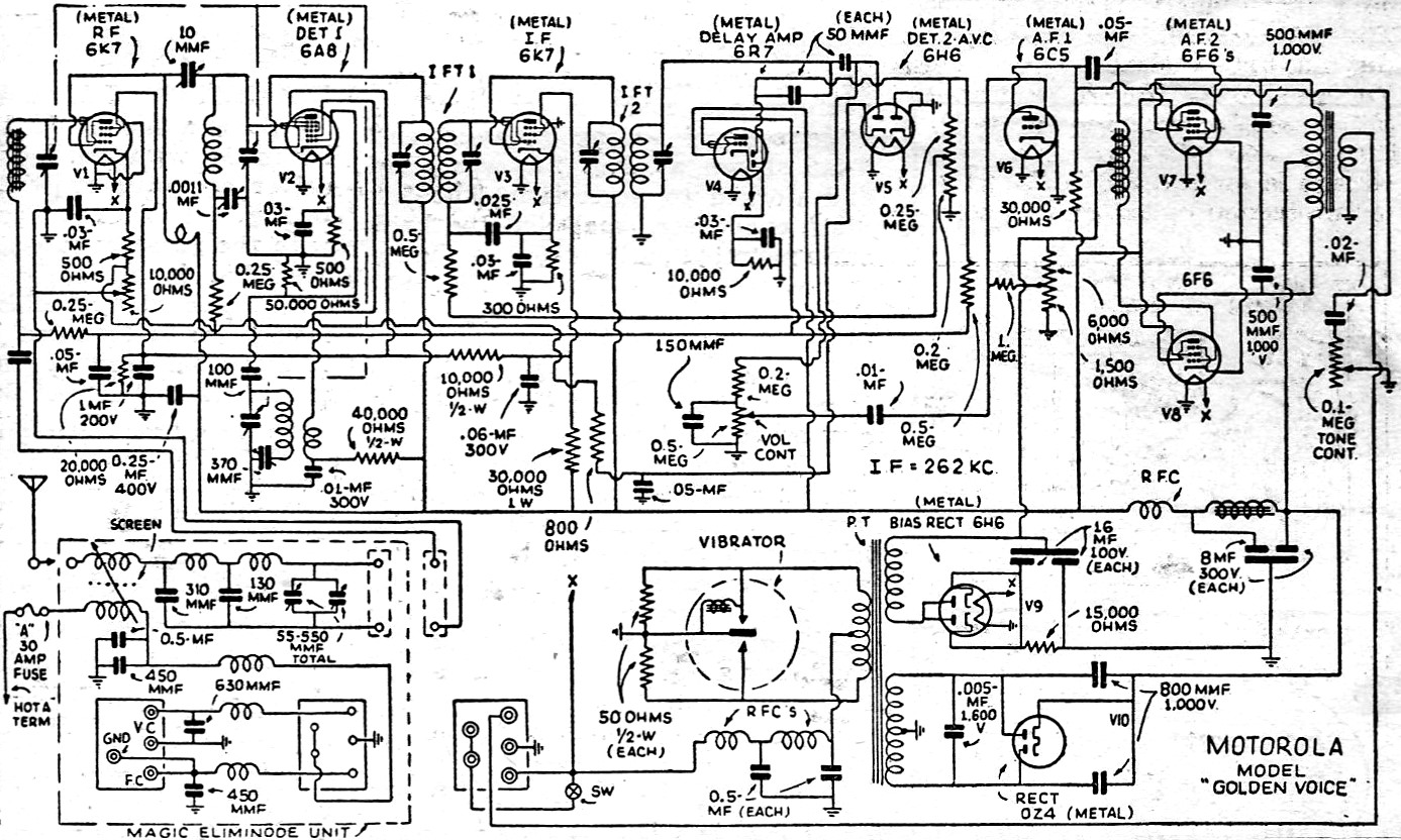
 (7) Motorola "Golden Voice" Model.
This set contains the "magic eliminode" circuit. which not only filters out motor
noise, but balances the noise out of the antenna lead, so that suppressorless operation
is possible on almost all cars. This unit also incorporates an antenna tuning circuit
to properly match and tune the set to any type of antenna. Besides the tone control
and the normal volume control, this set has a variable sensitivity control, which
is mounted on the front of the case. The input tuning coil of the R.F. stage is
of the iron-core type. The output stage is of the class AB type, with a separate
bias rectifier system, using a 6H6 with an independent filter. The bias from this
source is used on both A.F. stages. The circuit herewith published is the latest
and supersedes all others. Delayed A. V.C. is employed and is affected by the use
of V4 in conjunction with V5. Do not connect any condenser from the hot "A" lead
to ground as this would nullify the action of the eliminode. All necessary filtering
is contained in the latter. Current drain from a fresh battery is 8A., producing
250 V. (Photo on page 712.) (7) Motorola "Golden Voice" Model.
This set contains the "magic eliminode" circuit. which not only filters out motor
noise, but balances the noise out of the antenna lead, so that suppressorless operation
is possible on almost all cars. This unit also incorporates an antenna tuning circuit
to properly match and tune the set to any type of antenna. Besides the tone control
and the normal volume control, this set has a variable sensitivity control, which
is mounted on the front of the case. The input tuning coil of the R.F. stage is
of the iron-core type. The output stage is of the class AB type, with a separate
bias rectifier system, using a 6H6 with an independent filter. The bias from this
source is used on both A.F. stages. The circuit herewith published is the latest
and supersedes all others. Delayed A. V.C. is employed and is affected by the use
of V4 in conjunction with V5. Do not connect any condenser from the hot "A" lead
to ground as this would nullify the action of the eliminode. All necessary filtering
is contained in the latter. Current drain from a fresh battery is 8A., producing
250 V. (Photo on page 712.)
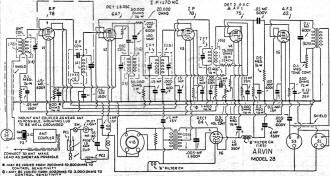 (8) Arvin Model 28. This
set may be had with either enclosed or separate speaker. Also matching dash control
panels may be had, or the set may be equipped with a streamline steering-column
control. A complete noise filter is built-in. Special iron-core antenna tuning system
consists of two couplers assuring high gain on the smallest antenna. Full A.V.C.
holds signal steady, while continuously-variable tone control covers complete tonal
range. The set must be balanced at 1,400 kc., and checked for accuracy at 1,000
and 600 kc. Tubular fixed condensers are firmly fastened to chassis, eliminating
broken leads. Copper plated chassis and case with locking snap-on covers add to
stability and ease of servicing. Only one hole to drill to install chassis in any
position, back or side. Tuning condenser is rubber mounted and has an improved high-ratio
vernier drive, enabling the greatest possible ease of tuning. Voltages: Plate -
V1, V2, V3, 235; V4, 120; V5, 230. S.-G. - V1, V2, V3, 90; V5, 235. Cath. - V1,
V2, 4; V3, 2.3; V4, 1.6; V5, 16. Osc. plate, V2, 160. (8) Arvin Model 28. This
set may be had with either enclosed or separate speaker. Also matching dash control
panels may be had, or the set may be equipped with a streamline steering-column
control. A complete noise filter is built-in. Special iron-core antenna tuning system
consists of two couplers assuring high gain on the smallest antenna. Full A.V.C.
holds signal steady, while continuously-variable tone control covers complete tonal
range. The set must be balanced at 1,400 kc., and checked for accuracy at 1,000
and 600 kc. Tubular fixed condensers are firmly fastened to chassis, eliminating
broken leads. Copper plated chassis and case with locking snap-on covers add to
stability and ease of servicing. Only one hole to drill to install chassis in any
position, back or side. Tuning condenser is rubber mounted and has an improved high-ratio
vernier drive, enabling the greatest possible ease of tuning. Voltages: Plate -
V1, V2, V3, 235; V4, 120; V5, 230. S.-G. - V1, V2, V3, 90; V5, 235. Cath. - V1,
V2, 4; V3, 2.3; V4, 1.6; V5, 16. Osc. plate, V2, 160.
Radio Service Data Sheets
These schematics, tuning instructions, and other data are reproduced from my
collection of vintage radio and electronics magazines. As back in the era, similar
schematic and service info was available for purchase from sources such as
SAMS Photofacts, but these printings
were a no-cost bonus for readers. There are 227 Radio Service Data Sheets as of
December 28, 2020.
-
AMRAD
Model 81 "Bel Canto"
-
GE
Model 250 Radio Service Data Sheet
- Hoffman
Model A300
- Emerson
Model 505
- Olympic
Models 6-501, 6-502, 6-503
- Radiola
Models 61-5, 61-10
- Farnsworth
Models ET-060, ET-061, ET-063
- General
Electric Model 321
-
Garod Model 6AU-1
- Truetone
Model D4620
- Westinghouse
Model H-148
- Wards Models
54BR-1501A, 1502A
- Majestic
Models 8S452, 8S473
- RCA Models
Q22A, Q32
- Zenith Model
5G003ZZ
- Mantola Models
92503 and 92504
- Emerson Model
508 Series 8-7434351 and Up
- Belmont Model
A-5D118
- Wards Model
74BR-2707A
- Crosley Model
56TP-L
- Admiral Model
7C60 Chassis 6B1
- 336
Belmont Radio Model 6D111, Series A
-
333 General Electric Models 100, 101, 103 and 105
- RCA Victor
Models 54B1, 54B-N, 54B2, 54B3 Radio Data Sheet 335
-
National Union "Presentation" Radio Model G-619
-
Zenith Radio Models 8H032, 8H033, 8H050, 8H052, 8H061
-
General Electric Farm Radio Model 280
-
Admiral Model 6RT44-7B1
-
Montgomery Ward Airline Model 04BR-1105A Radio
- Belmont
Model 678 Auto-Radio Set
- Sentinel
Model 217-P Portable Radio Set Radio
- Remler
Model No. 36 Dual-Wave Auto-Radio
-
Stromberg-Carlson No. 82 All-Wave Receiver
-
Majestic A.V.C. Model 290 Chassis
- FADA 9 Tube
Model 190 "Metal" All-Wave
- RCA Victor
Models 9T and K2 9-Tube, 5- to 566-Meter
-
Motorola "Golden Voice" Model
-
RCA Victor Model H-6
-
Simplex Model TA
-
Automatic "Magic Eye" Model A1
- Silvertone
Models 4488 and 4588 (Chassis No.101412) and 4488A and 4588A (Chassis No. 101412A)
- RCA Victor
Model M109 "De Luxe" 7-Tube Auto-Radio Receiver
- Crosley Model
6625 6-Tube 3-Band Receiver
- International
Model 77 Series 7-Tube Dual-Band Receiver
- Belmont
Model 6D121
-
General Electric Models 60, 62
- Admiral
Model 7C64
-
Radiola "28" Super and "104" Power Speaker
- Sonora
Model TW-49
-
Stromberg-Carlson Models 1020, 1120, Series 10
- Air King
Model 4604D
- Sparton Models
526, 526X, 526PS
- Truetone
Model D2624
- Admiral
Models 6EI, 6EIN
- Detrola Models
571A, 571B
-
General Electric Model 250
- Howard Model
920
- Colonial
Model 652 5-Tube Broadcast-Short-Wave
-
Fairbanks-Morse
9-Tube All-Wave Model 91
-
International Model 500 5-Tube Dual-Range Battery
- Emerson Model
678 "Auto-Dynamic" 5 Tube
-
Stromberg-Carlson
Nos. 230 and 231 Series
- Atwater
Kent Model 649 All-Wave
-
Howard Model G-26, and "Airplane 4" Model AA25
-
Montgomery Ward "Airline" Series 7GM 7-Tube High-Fidelity Receiver
- RCA
Victor Model T5-2 5-Tube, 2-Band A.C. Superheterodyne Receiver
-
Majestic
"Models 50," "51" and "52"
-
Bremer-Tully Model 7-70 and 7-71
-
General
Electric Model M-49 4-Tube Radio-Phonograph Dual-Wave Superheterodyne
- RCA-Victor
Radiola "Superette" Model R7 Superheterodyne
- Crosley Model AC-7
and AC-7C
-
Westinghouse
"Columnaire" Models WR-8 and WR-8-R (Remote Control)
-
Characteristics
of Metal Tubes - and Other "Octal" (8-Prong) Base Types
- Kolster K20,
K22, K25, K27 and K37 Six-Tube Receivers
-
Stromberg-Carlson
Nos. 62 and 63, 8-Tube High-Fidelity Chassis
- RCA Model
103, 4-Tube A.C. Compact Dual-Wave
- FADA "Special"
Model 265-A and FADA "7" Model 475-A
-
General Electric Model C-62 6-Tube Battery
- Emerson
5A Automotive
- Zenith
666 Automotive
- Motorola
100 Automotive
-
Crosley
Roamio 4-A-1 Automotive
-
American-Bosch
524A Automotive
- Crosley
Model 1316 (in Model 167 Console)
- RCA Victor
"High-Fidelity Electrola," Model R-99
- AMRAD
Model 81 ("Bel Canto" Series) Receiver
-
Fada 103 Fadalette, Stewart-Warner Series 108, DeWald 54 Dynette Sets
- RCA
Victor R-27 and Philco 53 Ultra-Midget A.C.-D.C. Radio Receivers
-
Majestic Models Fairfax and Sheffield 8-Tube
- Stromberg-Carlson
No. 29, 9-Tube Superhet
-
International Kadette Model 400 4-Tube Battery-Operated Superhet
- RCA Victor
Model 5M 5-Tube Auto Superhet
-
Majestic Model 11 Short-Wave Converter
-
Silver-Marshall
Model 727-DC Battery-Operated Superheterodyne
- RCA
Victor Model VHR-307 Home Recording - Phono-Radio Combination
-
Delco 32-Volt Radio Receiver Chassis Models RA-3, RB-3 and RC-3
- Majestic
Chassis Models 380 A.C. T.R.F., and 400 A.C.-D.C. Superheterodyne
- General
Motors S1A, S1B
- Admiral
Model 7C63, Chassis 7C1
- Westinghouse
Model H-133
- Arvin
Models 150TC, 151TC
- Kadette Model
90 Duplex
-
RCA-Victor "Magic Brain" Model 281
- Grunow
11A Chassis 11-Tube All-Wave Superheterodyne
-
Sears, Roebuck & Co., Silvertone "Rocket" Models 6110 and 6111
-
General Electric Model GD-52
-
Zenith Models 6D302, 6D311, 6D326, 6D336, 6D360
-
Allied Radio, Knight Model E10913
- Arvin Model
140P
- Emerson
Models 501, 502, 504
- Crosley
Model 56TD-W
- Hoffman
Model A500
-
Stewart-Warner
Model 9003-B
-
Zenith Models 6D014, 6D029
- Coronet
Model C-2
- Sparton
Models 7-46, 7-46PA, 8-46, 8-46PA
-
Stewart-Warner Models 9001-C, D, E, F
-
Zenith Models 5D011-5D027
- Bendix Models
636A, C, D
- ECA Model 108
-
International Model 66 and 666, 6-Tube Superhet
-
Ford-Philco
Radio, Model FT9, 6-Tube Auto-Radio Receiver
- Howard
Explorer Model W Deluxe 19 Tube All-Wave Superhet
- RCA Victor
Portable Table Electrola Model R-95
- Atwater
Kent Model 305Z 5-Tube 32 V. D.C. Superhet
- Kadette
Jewel Model 40 Chassis 3-Tube Ultra-Midget Receivers
-
General Electric Model N-60 6-Tube Auto Superheterodyne
-
Sparton Model 40 6-Tube T.R.F. Automotive Receiver
-
Clarion "Replacement" Chassis, Model AC-160 A.V.C. Superheterodyne
- Emerson Models
20A and 25A
- General
Electric K-40A
- Pilot Model
B-2
- RCA-Victor
Radiola Model M-30 Automotive Radio
- Motovox
Models 10A All-Electric and 10E Battery-Operated "Moto-Tetradynes"
-
Kennedy Superheterodyne Short-Wave Converter
- RCA
Victor Model R-78 B1-Acoustic 12-Tube
- Philco
Model 15 Series, 11-Tube Superheterodyne Chassis
-
Zenith Challenger Model 740
-
Sparton
Selectronne Receivers Models 1068 and 1068X
- Fada Model
155 Super Fadalette A.C.-D.C. Set
-
Clarion De Luxe Models AC-280 and 25-280
-
Crosley Model A-157 (River Roamio) Auto Radio
- Philco Model
'37-116 Codes 121 (Shadometer) and 122 (Dial Tuning)
-
Arvin Model 28
-
Philco Model 818
-
Fada Model 266 Motoset
-
Bosch Models 736, 737, 738
- RCA-Victor
Model 15U, Radio-Phonograph
- Sparton
Models 566 ("Bluebird" Mirror), A.C.-D.C. 5-Tube 2-Band Midget Superhet
- Atwater
Kent Model 776 6-Tube Auto Radio
- Stromberg-Carlson
No. 61 4-Band 7-Tube A.C.-D.C. Receiver
- Arvin Model
182TFM
- Crosley
Model 58TK
- Westinghouse
Model H-165
-
General Electric Models G-105 and G-106
- Silvertone
"F," "FF," "G," "H," and "J"
-
Stewart-Warner Model 03-5A1 to 03-5A9 (Chassis 03-5A) Senior Varsity Radio
- Radiola Models
61-6, 61-7
-
Westinghouse
Models H-104, H-105, H-107, H-108
- Farnsworth
Models EC-260, EK-262, EK-263, EK-264, EK-265
-
United
Models 980744, 980745
-
Stewart-Warner (R-127 Chassis) Models 1271 to 1279 All-Wave
- ERLA Model
4500 Dual-Wave T.R.F. 4-Tube A.C. Receiver
- Clarion No. TC-31
5-Tube A.C.-D.C. Superhet.
- Detrola Model
105C 5-Tube Dual-Band A.C.-D.C.
- Zenith
6-Tube All-Wave Chassis No. 5634
- RCA Victor
Model 261, 555 to 107 Meter
- Philco
Model 38-116; Code 125
-
Stewart-Warner "Ferrodyne" Chassis Model R-136
-
American-Bosch
Model 43OT 5-Tube 3-Band Superheterodyne
- RCA
Victor Model C9-4 9-Tube 3-Band Superheterodyne
- Kennedy "Model
826B" Combination Receiver
- Steinite
50-A and 102-A
- Pilot Model
63 All-Wave 6-Tube Superheterodyne
- Stromberg-Carlson
No. 69 4-Tube All-Wave Superhet. Selector (Converter)
- RCA
Victor Model 102 4-Tube A.C.-D.C. T.R.F. Receiver
- Bosch Models 60
and 61
-
Atwater Kent Models 30, 33, 35, 48 and 49
- Crosley Model
120 Senior Superheterodyne (Pliodynatron) Chassis
-
Columbia Screen-Grid 8 Receiver
-
General Electric Models A82 and A87, 8-Metal-Tube All-Wave A.C. Superhet.
- Colonial
31 and 32 D.C.
- Zenith 5-Tube
Triple-Wave Chassis nos. 5508 and 5509
- Remler Model
46 ("Scottie")
- General
Electric FA-60 and FA-61
-
Stewart-Warner
Series 900
-
Howard
Model B-5 (715), Series 1 and 2 (Sheaffer Radio-Clock-Pen Desk Set)
-
Ford-Philco Car-Radio Models F-1440 and F-1442
-
Brunswick Model 31 Combination Radio and Panatrope
- Emerson Models
38, 42 and 49, 6-Tube Dual-Wave (Chassis U6)
-
General Motors Chevrolet No. 601574 Automotive
-
RCA Victor M-104 (and M-108) Automotive
- Arvin-Ford
17-A Automotive
-
Westinghouse Model WR 207 & WR 208 5-Tube Dual-Band Superheterodyne
- Radiolas
"Super VIII" (AR-810, "Semi-Portable" (AR-812), 24 and 26
- Howard Model
45 A. V. C.
- Majestic
Model 25
-
Galvin Motorola Model 61
-
Arvin Model 6
- Admiral
Models 7T06, 7T12
- Garod Model 5A1
- Hoffman Model A301
-
Knight Model E10716 Battery Portable
- Arvin Models 555,
555A, 552N, 552AN
- Grantline Models
605, 606
- Truetone Model
D2616
- Belmont Model
5D128
- Arvin Models 444,
444A
-
International Kadette Model 1019
-
Stewart-Warner Models 97-561 to 97-569
- General
Electric Model 280
- Zenith Models 5R080,
5R086
- Truetone Models
D1747, D1748
-
Crosley Roamio Automotive T.R.F. Models 90, 91, 92
-
Crosley Roamio Automotive Superheterodyne Models 95, 96
-
Wells-Gardner Series 062
-
Emerson
Model AZ-196
- Belmont Model
5P19
- Crosley
Fortyfive
- Crosley Model
56FC
-
Emerson
Models 507, 509, 518, 522, 535
- Garod Model 6AU-1
- General
Electric Models 219, 202, 221
-
Crosley "Chairside" Model 567
-
Belmont Model 408 Battery "Farm"
- Wards Model
74BR-1055A
- Farnsworth
Models EK-081, EK-082, EK-083, EK-681
- Philco
Model 200-X Radio
-
Admiral "Aeroscope" Models 161-5L, 162-5L and 163-5L
- Philco
Model 59, 4-Tube A.C. Midget Superheterodyne
- Zenith
Farm Model 6V 27, 6-Tube Superhet
- Ward 10-Tube
All-Wave High-Fidelity Superhet, Series ODM
-
Philco-Packard
Deluxe
-
Canadian
Westinghouse Model 175
- Crosley Model
1155
- Philco Models
39 and 39A
-
Arvin Model 35 8-Tube Car-Radio
- Hetro
Air-Ace Series M
- Westinghouse
Models H-161, H-168, H-168A
- Garod Model 5A4
- Arvin Models 152T,
153T
- Belmont Model 5240
- Mantola Models 92505,
92506
- General Electric
Models 102, 102W, 107, 107W, 114, 114W, 115, 115W
- Crosley Model
555 (A.F.M.)
- Crosley Model
515 (Fiver)
- Crosley Model
425 (Travo)
-
Firestone-Stewart-Warner Model R1332
- Fairbanks-Morse
Model 81 "Farm" Set
- Clarion Model
423, 470, 471, 472, 480
-
International Radio Corp. Model 90
- Belmont Model
578 Series A
Posted January 17, 2024
(updated from original
post on 8/3/2017)
|