|
February 1932 Radio-Craft
 [Table
of Contents] [Table
of Contents]
Wax nostalgic about and learn from the history of early electronics.
See articles from Radio-Craft,
published 1929 - 1953. All copyrights are hereby acknowledged.
|
Once again I have given
selflessly and freely of my time and talent to make available resources to those
seeking certain knowledge regarding vintage radio circuits ;-) This time it is
the Radio Service Data Sheet for the Howard Model 45 superheterodyne radio
receiver featuring an AVH-style chassis A.V.C. with A.V.C. (automatic volume
control). The info was published in a 1932 edition of Radio-Craft magazine, one
of Hugo Gernsback's many endeavors. An extensive Internet search did not turn up
any examples of surviving of the Howard Model 45 AVH. Please send me a note if
you of one. Also, at the bottom of this page is a complete list of all such
schematics and tuning and repair data posted thus far.
Howard Model 45 A.V.C. Superheterodyne with Model A.V.H. Chassis
Radio Service Data Sheet
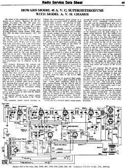 The values of the components of this receiver
chassis are as follows: Resistors R1 , R3, R5, 1/5-meg. (1/3-watt); R2, R6, 500
ohms (1/5-watt); R4, 6,000 ohms (1/2-watt); R7, 30,000 ohms; R8, volume control,
1/2-meg.; R9, 1/2-meg.; R10, 3,000 ohms; R11, 2,000 ohms; R12, R13, 150,000 ohms
(1/2-watt); R14, 2 megs.; R15- R16-R17-R18-R19, voltage divider, 9,900 ohms; R20,
R21, 10 ohms (center-tapped); R22, 200 ohms. The values of the components of this receiver
chassis are as follows: Resistors R1 , R3, R5, 1/5-meg. (1/3-watt); R2, R6, 500
ohms (1/5-watt); R4, 6,000 ohms (1/2-watt); R7, 30,000 ohms; R8, volume control,
1/2-meg.; R9, 1/2-meg.; R10, 3,000 ohms; R11, 2,000 ohms; R12, R13, 150,000 ohms
(1/2-watt); R14, 2 megs.; R15- R16-R17-R18-R19, voltage divider, 9,900 ohms; R20,
R21, 10 ohms (center-tapped); R22, 200 ohms.
Condensers C4, C5, C6, C7, I.F. trimmers; C8, C9, C10, C15, C16, 0.1·mf.; C11,
0.00025-mf.; C12, 0.001-mf.; C17, C18, 0.25-mf.; C19, C23, 0.5-mf.; C21, 0.05-mf.;
C24, 1.0 mf.; C25, C26, 8 mf. (420 volts); C27, 4 mf. (420 volts).
In the interest of obtaining best results with the Automatic Volume Control receiver,
it is important that the type '27 control tube V9 be a selected one, with a definite
plate current cut-off when tested at 180 volts plate and 20 volts bias on the grid.
This cut-off should be less than 5 microamperes. If there is no means available
for checking the tube (in the form of a special tube tester), an immediate check
for tube performance can be obtained in the set itself.
For instance, disconnect the antenna and short-circuit the aerial lead, leaving
the control tube out of the socket, and note the swing of the tuning meter. Then
insert the tube in the socket and if it is a good automatic volume control tube,
there should be no change in the position of the pointer on the tuning meter. If
there is a change in the position of the tuning meter pointer, namely, a swing toward
the right, it is an indication that the A. V. C. tube does not have a definite plate
cut-off; instead, it is drawing plate current and as a result the bias voltage on
the regular R.F. and I.F. tubes has been raised, with the consequent cutting down
in plate current.
The Model 45 speaker has a 350-ohm field, and as such it cannot be used with
the Models 35 and 40 receivers.
The receiver housed in the regular cabinet is the "Model 45"; the chassis is
the "Model AVH."
The automatic volume control functions in holding the second-detector input voltage
at a definite level, a system which is different from that in other receivers. A
reduction of background noises, between stations, will be noted.
The only service met with to date on the Model "H" receiver has been in connection
with the shorting out of the R.F. plate bypass condenser, the red lead of which
may accidentally become wedged underneath the first I.F. coil can. The insulation
does not cut through immediately but, after being in service for a number of days,
the pressure on the insulation may be such as to gradually cut through it, shorting
out the plate bypass condenser, and thus producing zero voltage on the plates of
the R.F., first detector, and I.F. tubes.
The A. V. C. tube is so connected by means of a 2-megohm resistor, R14, that
the grid is at absolute "B-" potential. The cathode of the tube is connected to
a point on the voltage divider which is at 24 volts positive, with respect to "B-"
or the grid. There then exists between the cathode and the grid a potential difference
of 24 volts with the grid negative by this amount. The plate of this tube connects
to ground by means of two 150,000-ohm resistors, R12-R13. Since ground is connected
to 124 volts, positive (with respect to "B-"), there exists between the cathode
and the plate a potential difference of 100 volts. In order to bypass any R. F.
energy which may appear on the plate, a non-inductive condenser C22 is connected
from the plate of the A. V. C. tube to the cathode.
With the condition of no-signal there exists a bias of 24 volts and a plate potential
of 100 volts. Under these conditions, there is no plate current flowing and the
tube is said to be adjusted to cut-off. Since no plate current is flowing, there
exists no voltage drop across the plate circuit resistors and, therefore, there
is no bias voltage on the grids of the controlled tubes. The only bias on the R.F.,
first detector, and I.F. is caused by the respective voltage drops across their
cathode resistors. These resistors are designed to give the most sensitive operating
point.
In the case of a received signal, energy passes through the receiver to the second-detector
grid. Here the A. V. C. (automatic volume control) tube grid, and the second-detector
grid, are in parallel. The signal voltage is fed to the grid of the A. V. C. tube
through a small fixed condenser, C11.
It will be seen that during the positive half of the incoming cycle, the peak
voltage of the signal swing subtracts from the original bias voltage; which means
that the instantaneous bias on the tube is less than the original bias and the tube
begins to draw current in its plate circuit. Since this current flows in the resistors
in the plate circuit of the A. V. C. tube, there exists a voltage drop across these
resistors; also, the flow of the electrons is from plate to ground so that the plate
becomes negative with respect to ground. Now, since the original potential of the
cathode of the R.F., first-detector, and I.F. tubes is positive with respect to
ground, it follows that if the grids of the respective tubes are connected to a
resistor in the plate circuit of the A. V. C. tube, that any potential existing
across this resistor is added to the original bias and makes the grids more negative
than the original bias by the amount of the voltage drop across the resistor in
the A. V. C. tube plate.
It is at once apparent that the greater the signal voltage appearing at the grid
of the A. V. C. tube, the more plate current will flow in the plate circuit: an
increase in plate current means an increase in bias on the R.F., first-detector,
and I.F. tubes; an increased bias on these tubes means less amplification and, therefore,
less grid swing on the second-detector and A. V. C. tube. This cycle goes on until
a constant voltage is obtained across the second-detector input, or, in other words,
until a condition of equilibrium is reached.
Since R8 is located where the tone control is normally connected, it was necessary
to relocate the tone control, C13-R9-C14. As less resistance is included between
the two condensers, they become more effective in bypassing the higher audio frequencies;
at the same time, they resonate the primary of T2 to a lower audio frequency.
Posted August 3, 2023
(updated from original post
on 2/25/2015)
Radio Service Data Sheets
These schematics, tuning instructions, and other data are reproduced from my
collection of vintage radio and electronics magazines. As back in the era, similar
schematic and service info was available for purchase from sources such as
SAMS Photofacts, but these printings
were a no-cost bonus for readers. There are 227 Radio Service Data Sheets as of
December 28, 2020.
-
AMRAD
Model 81 "Bel Canto"
-
GE
Model 250 Radio Service Data Sheet
- Hoffman
Model A300
- Emerson
Model 505
- Olympic
Models 6-501, 6-502, 6-503
- Radiola
Models 61-5, 61-10
- Farnsworth
Models ET-060, ET-061, ET-063
- General
Electric Model 321
-
Garod Model 6AU-1
- Truetone
Model D4620
- Westinghouse
Model H-148
- Wards Models
54BR-1501A, 1502A
- Majestic
Models 8S452, 8S473
- RCA Models
Q22A, Q32
- Zenith Model
5G003ZZ
- Mantola Models
92503 and 92504
- Emerson Model
508 Series 8-7434351 and Up
- Belmont Model
A-5D118
- Wards Model
74BR-2707A
- Crosley Model
56TP-L
- Admiral Model
7C60 Chassis 6B1
- 336
Belmont Radio Model 6D111, Series A
-
333 General Electric Models 100, 101, 103 and 105
- RCA Victor
Models 54B1, 54B-N, 54B2, 54B3 Radio Data Sheet 335
-
National Union "Presentation" Radio Model G-619
-
Zenith Radio Models 8H032, 8H033, 8H050, 8H052, 8H061
-
General Electric Farm Radio Model 280
-
Admiral Model 6RT44-7B1
-
Montgomery Ward Airline Model 04BR-1105A Radio
- Belmont
Model 678 Auto-Radio Set
- Sentinel
Model 217-P Portable Radio Set Radio
- Remler
Model No. 36 Dual-Wave Auto-Radio
-
Stromberg-Carlson No. 82 All-Wave Receiver
-
Majestic A.V.C. Model 290 Chassis
- FADA 9 Tube
Model 190 "Metal" All-Wave
- RCA Victor
Models 9T and K2 9-Tube, 5- to 566-Meter
-
Motorola "Golden Voice" Model
-
RCA Victor Model H-6
-
Simplex Model TA
-
Automatic "Magic Eye" Model A1
- Silvertone
Models 4488 and 4588 (Chassis No.101412) and 4488A and 4588A (Chassis No. 101412A)
- RCA Victor
Model M109 "De Luxe" 7-Tube Auto-Radio Receiver
- Crosley Model
6625 6-Tube 3-Band Receiver
- International
Model 77 Series 7-Tube Dual-Band Receiver
- Belmont
Model 6D121
-
General Electric Models 60, 62
- Admiral
Model 7C64
-
Radiola "28" Super and "104" Power Speaker
- Sonora
Model TW-49
-
Stromberg-Carlson Models 1020, 1120, Series 10
- Air King
Model 4604D
- Sparton Models
526, 526X, 526PS
- Truetone
Model D2624
- Admiral
Models 6EI, 6EIN
- Detrola Models
571A, 571B
-
General Electric Model 250
- Howard Model
920
- Colonial
Model 652 5-Tube Broadcast-Short-Wave
-
Fairbanks-Morse
9-Tube All-Wave Model 91
-
International Model 500 5-Tube Dual-Range Battery
- Emerson Model
678 "Auto-Dynamic" 5 Tube
-
Stromberg-Carlson
Nos. 230 and 231 Series
- Atwater
Kent Model 649 All-Wave
-
Howard Model G-26, and "Airplane 4" Model AA25
-
Montgomery Ward "Airline" Series 7GM 7-Tube High-Fidelity Receiver
- RCA
Victor Model T5-2 5-Tube, 2-Band A.C. Superheterodyne Receiver
-
Majestic
"Models 50," "51" and "52"
-
Bremer-Tully Model 7-70 and 7-71
-
General
Electric Model M-49 4-Tube Radio-Phonograph Dual-Wave Superheterodyne
- RCA-Victor
Radiola "Superette" Model R7 Superheterodyne
- Crosley Model AC-7
and AC-7C
-
Westinghouse
"Columnaire" Models WR-8 and WR-8-R (Remote Control)
-
Characteristics
of Metal Tubes - and Other "Octal" (8-Prong) Base Types
- Kolster K20,
K22, K25, K27 and K37 Six-Tube Receivers
-
Stromberg-Carlson
Nos. 62 and 63, 8-Tube High-Fidelity Chassis
- RCA Model
103, 4-Tube A.C. Compact Dual-Wave
- FADA "Special"
Model 265-A and FADA "7" Model 475-A
-
General Electric Model C-62 6-Tube Battery
- Emerson
5A Automotive
- Zenith
666 Automotive
- Motorola
100 Automotive
-
Crosley
Roamio 4-A-1 Automotive
-
American-Bosch
524A Automotive
- Crosley
Model 1316 (in Model 167 Console)
- RCA Victor
"High-Fidelity Electrola," Model R-99
- AMRAD
Model 81 ("Bel Canto" Series) Receiver
-
Fada 103 Fadalette, Stewart-Warner Series 108, DeWald 54 Dynette Sets
- RCA
Victor R-27 and Philco 53 Ultra-Midget A.C.-D.C. Radio Receivers
-
Majestic Models Fairfax and Sheffield 8-Tube
- Stromberg-Carlson
No. 29, 9-Tube Superhet
-
International Kadette Model 400 4-Tube Battery-Operated Superhet
- RCA Victor
Model 5M 5-Tube Auto Superhet
-
Majestic Model 11 Short-Wave Converter
-
Silver-Marshall
Model 727-DC Battery-Operated Superheterodyne
- RCA
Victor Model VHR-307 Home Recording - Phono-Radio Combination
-
Delco 32-Volt Radio Receiver Chassis Models RA-3, RB-3 and RC-3
- Majestic
Chassis Models 380 A.C. T.R.F., and 400 A.C.-D.C. Superheterodyne
- General
Motors S1A, S1B
- Admiral
Model 7C63, Chassis 7C1
- Westinghouse
Model H-133
- Arvin
Models 150TC, 151TC
- Kadette Model
90 Duplex
-
RCA-Victor "Magic Brain" Model 281
- Grunow
11A Chassis 11-Tube All-Wave Superheterodyne
-
Sears, Roebuck & Co., Silvertone "Rocket" Models 6110 and 6111
-
General Electric Model GD-52
-
Zenith Models 6D302, 6D311, 6D326, 6D336, 6D360
-
Allied Radio, Knight Model E10913
- Arvin Model
140P
- Emerson
Models 501, 502, 504
- Crosley
Model 56TD-W
- Hoffman
Model A500
-
Stewart-Warner
Model 9003-B
-
Zenith Models 6D014, 6D029
- Coronet
Model C-2
- Sparton
Models 7-46, 7-46PA, 8-46, 8-46PA
-
Stewart-Warner Models 9001-C, D, E, F
-
Zenith Models 5D011-5D027
- Bendix Models
636A, C, D
- ECA Model 108
-
International Model 66 and 666, 6-Tube Superhet
-
Ford-Philco
Radio, Model FT9, 6-Tube Auto-Radio Receiver
- Howard
Explorer Model W Deluxe 19 Tube All-Wave Superhet
- RCA Victor
Portable Table Electrola Model R-95
- Atwater
Kent Model 305Z 5-Tube 32 V. D.C. Superhet
- Kadette
Jewel Model 40 Chassis 3-Tube Ultra-Midget Receivers
-
General Electric Model N-60 6-Tube Auto Superheterodyne
-
Sparton Model 40 6-Tube T.R.F. Automotive Receiver
-
Clarion "Replacement" Chassis, Model AC-160 A.V.C. Superheterodyne
- Emerson Models
20A and 25A
- General
Electric K-40A
- Pilot Model
B-2
- RCA-Victor
Radiola Model M-30 Automotive Radio
- Motovox
Models 10A All-Electric and 10E Battery-Operated "Moto-Tetradynes"
-
Kennedy Superheterodyne Short-Wave Converter
- RCA
Victor Model R-78 B1-Acoustic 12-Tube
- Philco
Model 15 Series, 11-Tube Superheterodyne Chassis
-
Zenith Challenger Model 740
-
Sparton
Selectronne Receivers Models 1068 and 1068X
- Fada Model
155 Super Fadalette A.C.-D.C. Set
-
Clarion De Luxe Models AC-280 and 25-280
-
Crosley Model A-157 (River Roamio) Auto Radio
- Philco Model
'37-116 Codes 121 (Shadometer) and 122 (Dial Tuning)
-
Arvin Model 28
-
Philco Model 818
-
Fada Model 266 Motoset
-
Bosch Models 736, 737, 738
- RCA-Victor
Model 15U, Radio-Phonograph
- Sparton
Models 566 ("Bluebird" Mirror), A.C.-D.C. 5-Tube 2-Band Midget Superhet
- Atwater
Kent Model 776 6-Tube Auto Radio
- Stromberg-Carlson
No. 61 4-Band 7-Tube A.C.-D.C. Receiver
- Arvin Model
182TFM
- Crosley
Model 58TK
- Westinghouse
Model H-165
-
General Electric Models G-105 and G-106
- Silvertone
"F," "FF," "G," "H," and "J"
-
Stewart-Warner Model 03-5A1 to 03-5A9 (Chassis 03-5A) Senior Varsity Radio
- Radiola Models
61-6, 61-7
-
Westinghouse
Models H-104, H-105, H-107, H-108
- Farnsworth
Models EC-260, EK-262, EK-263, EK-264, EK-265
-
United
Models 980744, 980745
-
Stewart-Warner (R-127 Chassis) Models 1271 to 1279 All-Wave
- ERLA Model
4500 Dual-Wave T.R.F. 4-Tube A.C. Receiver
- Clarion No. TC-31
5-Tube A.C.-D.C. Superhet.
- Detrola Model
105C 5-Tube Dual-Band A.C.-D.C.
- Zenith
6-Tube All-Wave Chassis No. 5634
- RCA Victor
Model 261, 555 to 107 Meter
- Philco
Model 38-116; Code 125
-
Stewart-Warner "Ferrodyne" Chassis Model R-136
-
American-Bosch
Model 43OT 5-Tube 3-Band Superheterodyne
- RCA
Victor Model C9-4 9-Tube 3-Band Superheterodyne
- Kennedy "Model
826B" Combination Receiver
- Steinite
50-A and 102-A
- Pilot Model
63 All-Wave 6-Tube Superheterodyne
- Stromberg-Carlson
No. 69 4-Tube All-Wave Superhet. Selector (Converter)
- RCA
Victor Model 102 4-Tube A.C.-D.C. T.R.F. Receiver
- Bosch Models 60
and 61
-
Atwater Kent Models 30, 33, 35, 48 and 49
- Crosley Model
120 Senior Superheterodyne (Pliodynatron) Chassis
-
Columbia Screen-Grid 8 Receiver
-
General Electric Models A82 and A87, 8-Metal-Tube All-Wave A.C. Superhet.
- Colonial
31 and 32 D.C.
- Zenith 5-Tube
Triple-Wave Chassis nos. 5508 and 5509
- Remler Model
46 ("Scottie")
- General
Electric FA-60 and FA-61
-
Stewart-Warner
Series 900
-
Howard
Model B-5 (715), Series 1 and 2 (Sheaffer Radio-Clock-Pen Desk Set)
-
Ford-Philco Car-Radio Models F-1440 and F-1442
-
Brunswick Model 31 Combination Radio and Panatrope
- Emerson Models
38, 42 and 49, 6-Tube Dual-Wave (Chassis U6)
-
General Motors Chevrolet No. 601574 Automotive
-
RCA Victor M-104 (and M-108) Automotive
- Arvin-Ford
17-A Automotive
-
Westinghouse Model WR 207 & WR 208 5-Tube Dual-Band Superheterodyne
- Radiolas
"Super VIII" (AR-810, "Semi-Portable" (AR-812), 24 and 26
- Howard Model
45 A. V. C.
- Majestic
Model 25
-
Galvin Motorola Model 61
-
Arvin Model 6
- Admiral
Models 7T06, 7T12
- Garod Model 5A1
- Hoffman Model A301
-
Knight Model E10716 Battery Portable
- Arvin Models 555,
555A, 552N, 552AN
- Grantline Models
605, 606
- Truetone Model
D2616
- Belmont Model
5D128
- Arvin Models 444,
444A
-
International Kadette Model 1019
-
Stewart-Warner Models 97-561 to 97-569
- General
Electric Model 280
- Zenith Models 5R080,
5R086
- Truetone Models
D1747, D1748
-
Crosley Roamio Automotive T.R.F. Models 90, 91, 92
-
Crosley Roamio Automotive Superheterodyne Models 95, 96
-
Wells-Gardner Series 062
-
Emerson
Model AZ-196
- Belmont Model
5P19
- Crosley
Fortyfive
- Crosley Model
56FC
-
Emerson
Models 507, 509, 518, 522, 535
- Garod Model 6AU-1
- General
Electric Models 219, 202, 221
-
Crosley "Chairside" Model 567
-
Belmont Model 408 Battery "Farm"
- Wards Model
74BR-1055A
- Farnsworth
Models EK-081, EK-082, EK-083, EK-681
- Philco
Model 200-X Radio
-
Admiral "Aeroscope" Models 161-5L, 162-5L and 163-5L
- Philco
Model 59, 4-Tube A.C. Midget Superheterodyne
- Zenith
Farm Model 6V 27, 6-Tube Superhet
- Ward 10-Tube
All-Wave High-Fidelity Superhet, Series ODM
-
Philco-Packard
Deluxe
-
Canadian
Westinghouse Model 175
- Crosley Model
1155
- Philco Models
39 and 39A
-
Arvin Model 35 8-Tube Car-Radio
- Hetro
Air-Ace Series M
- Westinghouse
Models H-161, H-168, H-168A
- Garod Model 5A4
- Arvin Models 152T,
153T
- Belmont Model 5240
- Mantola Models 92505,
92506
- General Electric
Models 102, 102W, 107, 107W, 114, 114W, 115, 115W
- Crosley Model
555 (A.F.M.)
- Crosley Model
515 (Fiver)
- Crosley Model
425 (Travo)
-
Firestone-Stewart-Warner Model R1332
- Fairbanks-Morse
Model 81 "Farm" Set
- Clarion Model
423, 470, 471, 472, 480
-
International Radio Corp. Model 90
- Belmont Model
578 Series A
|