|
August 1964 Radio-Electronics
 [Table of Contents] [Table of Contents]
Wax nostalgic about and learn from the history of early electronics.
See articles from Radio-Electronics,
published 1930-1988. All copyrights hereby acknowledged.
|
Here are a couple electronics
circuit analysis problems to prime you for the week ahead. They are from the August
1964 "What's Your EQ?" challenge in Radio-Electronics magazine. EQ, by
the way, is for Electronics Quotient, as in IQ (Intelligence Quotient). Some others
are in the list below. In the Autotransformer problem, I made the assumption that
the secondary tap was actually in the middle (as drawn), so that there was an equal
number of turns above and below the tap. That proved to be a good assumption since
it validated my answer (not difficult if you know the basics of autotransformers).
The other problem, "Case of the Lost Energy," is a variation on similar ones containing
a potentially (pun intended) non-intuitive missing energy being stored in capacitors.
I'll admit to not having worked through it yet. You'll probably figure it out in
no time.
What's Your EQ?
 Conducted by E. D. Clark Conducted by E. D. Clark
Two puzzlers for the students, theoretician and practical man. Simple? Double-cheek
your answers before you say you've solved them. If you have an interesting or unusual
puzzle (with an answer) send it to us. We will pay $10 for each one accepted. We're
especially interested in service stinkers or engineering stumpers on actual electronic
equipment. We get so many letters we can't answer individual ones, but we'll print
the more interesting solutions - ones the original authors never thought of.
Write EQ Editor, Radio-Electronics, 154 West 14th Street, New York, N. Y. 10011
Answers to this month's puzzles are on page 60.
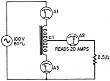 Autotransformer Autotransformer
Can you determine the reading on ammeter A1 and ammeter A3?
- Kendall Collins
Case of the Lost Energy
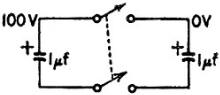 Here's a capacitor problem to test your ability
in analyzing "simple" circuits: Here's a capacitor problem to test your ability
in analyzing "simple" circuits:
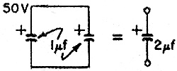
Two one-mike capacitors, and a switch connecting them. The left capacitor has
been charged up to 100 volts; the right one is unchanged. The switch is then closed.
Since we have not changed the total amount of charge, and since the theory book
tells us that:
Charge = Farads x Volts (Q = CE) the left capacitor will lose half of its charge
to the right one. The voltage will now be 50, since the capacitance has doubled.
The circuit now consists of a 2-μf capacitor charged to a potential of 50 volts.
So far, so good. Now once again, we refer to our theory book and find the formula
for the energy stored in a capacitor:
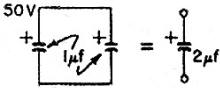 Energy = ½ x Farads x Volts2 Energy = ½ x Farads x Volts2
Let's try some numbers:
Originally,
Energy = ½ x 1 μf x 1002 + ½ x 1 μf x 02
= 2,500 μJoules
= 0.005 Joule
Finally,
Energy = ½ x 2 μf x 502
= 2,500 μJoule
= 0.0025 Joule!
We lost half the energy when we threw the switch! But a capacitor can only store
energy, not dissipate it. Also, our theory book is a firm believer in conservation
of energy.
Now then, simply, the problem:
Where did the energy go?
((Assume that the switch is perfect.)
- Donald E. Lancaster
Quizzes from vintage electronics magazines such as Popular
Electronics, Electronics-World, QST, and Radio News
were published over the years - some really simple and others not so simple. Robert P. Balin
created most of the quizzes for Popular Electronics. This is a listing
of all I have posted thus far.
- RF Cafe Quiz #71:
Tech Headlines for Week of 3/13/2023
- RF Cafe Quiz #70:
Analog &
RF Filter Basics
- RF Cafe Quiz #69:
RF
Electronics Basics
- RF Cafe Quiz #68:
RF & Analog Company Mergers & Acquisitions in 2017
- RF Cafe Quiz #67:
RF & Microwave Company Name Change History
- RF Cafe Quiz #66:
Spectrum and Network Measurements
- RF Cafe Quiz #65:
Troubleshooting & Repairing Commercial Electrical Equipment
- RF Cafe Quiz #64:
Space-Time Adaptive Processing for Radar
- RF Cafe Quiz #63:
Envelope Tracking Power Amplifiers
- RF Cafe Quiz #62:
Stimson's Introduction to Airborne Radar
- RF Cafe Quiz #61:
Practical Microwave Circuits
- RF Cafe Quiz #60:
Ten Essential Skills for Electrical Engineers
- RF Cafe Quiz #59:
Microwave Circulator Design
- RF Cafe Quiz #58:
Microwave and Millimeter-Wave Electronic Packaging
- RF Cafe Quiz #57:
Frequency-Agile Antennas for Wireless Communications
- RF Cafe Quiz #56:
Tube Testers
and Electron Tube Equipment
- RF Cafe Quiz #55:
Conquer
Radio Frequency
- RF Cafe Quiz #54:
Microwave Mixer Technology and Applications
- RF Cafe Quiz #53:
Chipless RFID Reader Architecture
- RF Cafe Quiz #52:
RF and Microwave Power Amplifiers
- RF Cafe Quiz #51:
Antennas and Site Engineering for Mobile Radio Networks
- RF Cafe Quiz #50:
Microstrip Lines and Slotlines
- RF Cafe Quiz #49:
High-Frequency Integrated Circuits
- RF Cafe Quiz #48:
Introduction to Infrared and Electro-Optical Systems
- RF Cafe Quiz #47:
LCP for Microwave Packages and Modules
- RF Cafe Quiz #46:
RF, Microwave, and Millimeter-Wave Components
- RF Cafe Quiz #45:
Dielectric and Thermal Properties of Materials at Microwave Frequencies
- RF Cafe Quiz #44:
Monopulse Principles and Techniques
- RF Cafe Quiz #43:
Plasma Antennas
- RF Cafe Quiz #42: The Micro-Doppler
Effect in Radar
- RF Cafe Quiz #41: Introduction
to RF Design Using EM Simulators
- RF Cafe Quiz #40: Introduction
to Antenna Analysis Using EM Simulation
- RF Cafe Quiz #39: Emerging
Wireless Technologies and the Future Mobile Internet
- RF Cafe Quiz #38: Klystrons,
Traveling Wave Tubes, Magnetrons, Crossed-Field Amplifiers, and Gyrotrons
- RF Cafe Quiz #37: Component
Reliability for Electronic Systems
- RF Cafe Quiz #36: Advanced
RF MEMS
- RF Cafe Quiz #35: Frequency
Synthesizers: Concept to Product
- RF Cafe Quiz #34: Multi-Gigabit
Microwave and Millimeter-Wave Wireless Communications
- RF Cafe Quiz #33: Battlespace
Technologies: Network-Enabled Information Dominance
- RF Cafe Quiz #32: Modern Communications
Receiver Design and Technology
- RF Cafe Quiz #31: Quantum
Mechanics of Nanostructures
- RF Cafe Quiz #30: OFDMA System
Analysis and Design
- RF Cafe Quiz #29: Cognitive
Radar
- RF Cafe Quiz #28: Human-Centered
Information Fusion
- RF Cafe Quiz #27: Remarkable
Engineers
- RF Cafe Quiz #26: Substrate
Noise Coupling in Analog/RF Circuits
- RF Cafe Quiz #25: Component
Reliability for Electronic Systems
- RF Cafe Quiz #24: Ultra Low
Power Bioelectronics
- RF Cafe Quiz #23: Digital
Communications Basics
- RF Cafe Quiz #22: Remember
the Basics?
- RF Cafe Quiz #21: Wireless
Standards Knowledge
- RF Cafe Quiz #20: Famous First
Names
- RF Cafe Quiz #19: Basic Circuit
Theory
- RF Cafe Quiz #18: Archaic
Scientific Words & Definitions
- RF Cafe Quiz #17: Inventors &
Their Inventions
- RF Cafe Quiz #16: Antennas
- RF Cafe Quiz #15: Numerical
Constants
- RF Cafe Quiz #14: Oscillators
- RF Cafe Quiz #13: General
Knowledge
- RF Cafe Quiz #12: Electronics
Corporations Headquarters
- RF Cafe Quiz #11: Famous Inventors &
Scientists
- RF Cafe Quiz #10: A Sampling
of RF & Wireless Topics
- RF Cafe Quiz #9: A Smorgasbord
of RF Topics
- RF Cafe Quiz #8: Hallmark Decades
in Electronics
- RF Cafe Quiz #7: Radar Fundamentals
- RF Cafe Quiz #6: Wireless Communications
Fundamentals
- RF Cafe Quiz #5: Company Logo
Recognition
- RF Cafe Quiz #4: General RF
Topics
- RF Cafe Quiz #3: General RF/Microwave
Topics
- RF Cafe Quiz #2: General RF
Topics
- RF Cafe Quiz #1: General RF
Knowledge
- Vacuum Tube Quiz,
February 1961 Popular Electronics
- Kool-Keeping Kwiz, June
1970 Popular Electronics
- Find the Brightest
Bulb Quiz, April 1960 Popular Electronics
-
Where Do the Scientists Belong? - Feb 19, 1949 Saturday Evening Post
|
-
What's Your EQ?
- March 1964 Radio-Electronics
-
What's Your EQ? - April 1962 Radio-Electronics
-
What's Your EQ? - May 1962 Radio-Electronics
-
What's Your EQ? - June 1962 Radio-Electronics
-
What's Your EQ? - April 1967 Radio-Electronics
-
What's Your EQ? - March 1967 Radio-Electronics
-
What's Your EQ? - December 1964 Radio-Electronics
-
What's Your EQ? - January 1967 Radio-Electronics
-
Wanted: 50,000 Engineers - January 1953 Popular Mechanics
-
What's Your EQ? - August 1964 Radio-Electronics
- Voltage Quiz
- December 1961 Popular Electronics
-
What is It? - June 1941 Popular Science
- What Do You Know
About Resistors? - April 1974 Popular Electronics
-
What's Your EQ? - September 1963 Radio-Electronics
- Potentiometer Quiz - September
1962 Popular Electronics
-
Mathematical Bafflers - March 1965 Mechanix Illustrated
- Op Amp Quiz -
October 1968 Popular Electronics
- Electronic "A"
Quiz - April 1968 Popular Electronics
-
What's Your EQ? - May 1961 Radio-Electronics
-
Popular Science Question Bee - February 1939 Popular Science
-
What is It? - A Question Bee in Photographs - June 1941 Popular Science
-
What's Your EQ? - June 1961 Radio-Electronics
-
What's Your EQ? - June 1964 Radio-Electronics
-
What's Your EQ? - May 1964 Radio-Electronics
-
What's Your EQ? - August 1963 Radio-Electronics
-
What's Your EQ? - May 1963 Radio-Electronics
- Bridge
Function Quiz - September 1969 Radio-Electronics
-
What's Your EQ? - March 1963 Radio-Electronics
-
What's Your EQ? - February 1967 Radio-Electronics
-
Circuit Quiz - June 1966 Radio-Electronics
-
What's Your EQ? - June 1966 Radio-Electronics
- Electronics
Mathematics Quiz - June 1969 Popular Electronics
- Brightest
Light Quiz - April 1964 Popular Electronics
-
What's Your EQ? - April 1963 Radio-Electronics
- Electronics "B" Quiz
- July 1969 Popular Electronics
- Ohm's Law Quiz
- March 1969 Popular Electronics
-
Antenna Quiz - November 1962 Electronics World
- Color Code Quiz
- November 1967 Popular Electronics
- CapaciQuiz
- August 1961 Popular Electronics
- Transformer
Winding Quiz - December 1964 Popular Electronics
-
Audiophile Quiz - November 1957 Radio-electronics
- Capacitor
Function Quiz - March 1962 Popular Electronics
- Greek Alphabet
Quiz - December 1963 Popular Electronics
- Circuit
Designer's Name Quiz - July 19680 Popular Electronics
-
Sawtooth Sticklers Quiz - November 1960 Radio-Electronics
-
Elementary
Radio Quiz - December 1947 Radio-Craft
- Hi-Fi
Quiz - October 1955 Radio & Television News
- Electronics Physics
Quiz - March 1974 Popular Electronics
- A Baffling Quiz
- January 1968 Popular Electronics
- Electronics IQ
Quiz - May 1967 Popular Electronics
- Plug and Jack
Quiz - December 1967 Popular Electronics
- Electronic
Switching Quiz - October 1967 Popular Electronics
- Electronic
Angle Quiz - September 1967 Popular Electronics
- International
Electronics Quiz - July 1967 Popular Electronics
- FM Radio
Quiz - April 1950 Radio & Television News
- Bridge Circuit
Quiz -December 1966 Popular Electronics
- Diode Function
Quiz - August 1965 Popular Electronics
- Diagram Quiz,
August 1966 Popular Electronics
- Quist Quiz - November
1953 QST
- TV Trouble Quiz,
July 1966 Popular Electronics
- Electronics History Quiz,
December 1965 Popular Electronics
- Scope-Trace Quiz,
March 1965 Popular Electronics
-
Electronic
Circuit Analogy Quiz, April 1973
-
Test Your Knowledge of Semiconductors, August 1972 Popular Electronics
- Ganged Switching
Quiz, April 1972 Popular Electronics
- Lamp Brightness
Quiz, January 1969 Popular Electronics
- Lissajous
Pattern Quiz, September 1963 Popular Electronics
- Electronic
Quizoo, October 1962 Popular Electronics
- Electronic
Photo Album Quiz, March 1963 Popular Electronics
- Electronic
Alphabet Quiz, May 1963 Popular Electronics
- Quiz: Resistive?
Inductive? or Capacitive?, October 1960 Popular Electronics
- Vector-Circuit
Matching Quiz, June 1970 Popular Electronics
- Inductance
Quiz, September 1961 Popular Electronics
- RC Circuit Quiz,
June 1963 Popular Electronics
- Diode Quiz, July
1961 Popular Electronics
- Electronic
Curves Quiz, February 1963 Popular Electronics
- Electronic
Numbers Quiz, December 1962 Popular Electronics
- Energy Conversion
Quiz, April 1963 Popular Electronics
- Coil Function
Quiz, June 1962 Popular Electronics
-
Co-Inventors Quiz - January 1965 Electronics World
-
"-Tron" Teasers Quiz - October 1963 Electronics World
- Polarity Quiz
- March 1968 Popular Electronics
-
Television
I.Q. Quiz - October 1948 Radio & Television News
- Amplifier Quiz
Part I - February 1964 Popular Electronics
- Semiconductor
Quiz - February 1967 Popular Electronics
- Unknown
Frequency Quiz - September 1965 Popular Electronics
- Electronics
Metals Quiz - October 1964 Popular Electronics
- Electronics
Measurement Quiz - August 1967 Popular Electronics
- Meter-Reading
Quiz, June 1966 Popular Electronics
- Electronic
Geometry Quiz, January 1965 Popular Electronics
- Electronic
Factor Quiz, November 1966 Popular Electronics
- Electronics
Math Quiz, November 1965 Popular Electronics
- Series Circuit
Quiz, May 1966 Popular Electronics
- Electrochemistry
Quiz, March 1966 Popular Electronics
- Biz
Quiz: Test Your Sales Ability - April 1947 Radio News
- Electronic
Analogy Quiz, November 1961 Popular Electronics
- Electronic
Coupling Quiz, August 1973 Popular Electronics
- Electronics
Analogy Quiz, August 1960 Popular Electronics
- Audio Quiz, April
1955 Popular Electronics
- Electronic Unit
Quiz, May 1962 Popular Electronics
- Capacitor
Circuit Quiz, June 1968 Popular Electronics
|
Answers to This month's puzzles are on page 47
Autotransformer
Ammeters A1 and A3 each read 10 amperes. The primary and secondary currents in
an autotransformer are 180° out of phase (in phase opposition). They tend to
cancel in the part of the primary winding which includes the secondary winding.
Taking into consideration a winding ratio of 2 to 1, and a secondary current
of 20 amperes, the apparent primary current (and hence the apparent reading on A1
and A3) would be 10 amperes. Since the primary and secondary are 180° out of
phase, the total primary current is the algebraic sum of the two, or 10 amperes.
Note: Core and winding losses are disregarded.
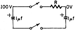
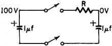 Case of the Lost Energy Case of the Lost Energy
This is really not as simple a problem as it looks. Suppose our problem circuit
looked like this instead.
Now, for a time after closing the switch, current will flow through the resistor
until the capacitor charges have become equal. Here in this resistor is a good place
to get rid of energy, turning it into heat. Since we must conserve energy, the heat
energy produced by the resistor evidently must be equal to the energy lost by the
capacitors. Now what if we change R to a different value? If R gets bigger, the
current flows for a longer time, but is weaker. If R gets smaller, the current flows
for a shorter time, but is stronger. The energy dissipated in the resistor is independent
of the value of the resistance and exactly equal to the difference between the initial
and final values of capacitor energy.
Because of this, if we have any resistance in the circuit at all, we have explained
where the energy went. In any practical problem, the small circuit lead resistance
would heat up and dissipate this energy. Since most energy values normally found
in capacitor circuits are generally very small, this heating effect is not very
noticeable. As an example, a 25-watt light bulb in 1 second dissipates or expends
25 joules of energy, or 10,000 times as much energy as that left in our capacitor
problem!
This explains any practical problem. But what if there were absolutely no resistance
in the circuit at all? Then there would be another way out of the problem. Near
absolute zero (-460°F), we may have zero circuit resistance. But always, no
matter what the temperature, we must have some lead inductance. Let's draw this
into the circuit.
But this is a resonant circuit! It will oscillate. If it oscillates, it will
radiate radio-frequency energy. And, the energy it radiates will be exactly equal
to the difference between the initial and final energy in the circuit.
Any reasonable value of lead resistance will damp this circuit and it will not
oscillate, so the resistance "wins" if it has half a chance.
Doodles in May 1964
The scope trace in the May 1964 issue can also be produced by quickly moving
the HORIZONTAL POSITION knob when the same frequency is put into both horizontal
and vertical inputs, out of phase so as to produce a circular Lissajous figure.
By noting whether the cusps are up or down, you can figure out whether the spot
is moving clockwise or counterclockwise. Thus you can tell which input, horizontal
or vertical, is leading and which is lagging. I have generated this pattern for
the purpose many times. -Paul Penfield, Jr.
Posted November 13, 2023
|