|
The 1954 Tournament of Roses
(aka Rose
Bowl Parade) was famously the world's first national
commercial color television broadcast, provided by the National
Broadcasting Company (NBC). Prior to the
NTSC (National Television
Systems Committee) finally settling on an all-electronic scheme for TV sets, many
electro-mechanical and electro-optical types were developed. The integrated RGB
(red, green, blue) color gun within a cathode ray tube (CRT) was a relatively new
concept in 1949. This Radio & Television News magazine article presents
some of the propositions by the two major research and development players at the
time: RCA and CBS. They might seem ridiculous in the light of knowledge available
now, but a round wheel wasn't immediately obvious to Oog sitting in his cave, trying
to figure out an easier way to transport that mastodon carcass. I wonder if Figure
9 was an early laboratory version of the
Sony Trinitron
picture tube?
Color Television?
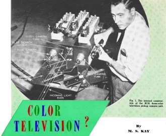
Fig. 1 - The internal construction of the RCA three-color
television pickup camera unit.
By M. S. Kay
A review of RCA and CBS color systems. Will either of these or some other color
system be chosen? Decision is, at present, in hands of FCC. It is likely that final
decision will be postponed indefinitely to permit further design development and
improvement.
Everyone knows that someday all television will be color television. Of this,
there is little doubt or dispute. The big question at the moment, however, is When?
Is color television ready now or are we technically premature? Can color television
be made compatible with our present black-and-white system or will it require an
entirely new set of standards, thereby obsoleting all present sets? It is for the
purpose of finding answers to these questions before the final u.h.f. allocations
are made that the present hearings are being conducted by the Federal Communications
Commission.
One of the most important stipulations that was made by the FCC concerning the
adoption of any color television system was that it should be as nearly compatible
to our present black-and-white system as possible. It is definitely not desired
that the 2,500,000 or more sets now in the hands of the public be made obsolete
by the introduction of a color television system.
The two major systems that are receiving the most consideration are those put
forth by RCA and CBS. The CBS system is essentially the same one developed and demonstrated
by this firm several years ago. The RCA system, however, is entirely new.

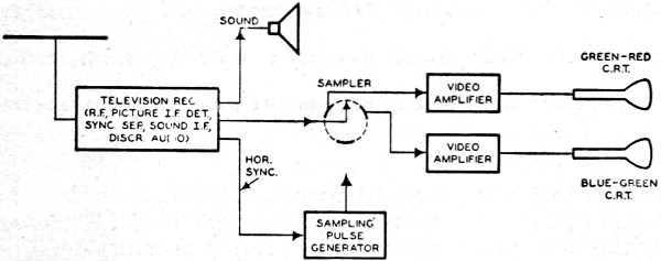
Fig. 2 - Block diagram of a possible two-color TV receiver.
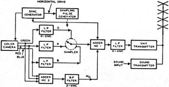
Fig. 3 - Block diagram of RCA's color television transmitter.

Fig. 4 - Method of operation employed in the sampler system.

Fig. 5 - A block diagram of a color television receiver.
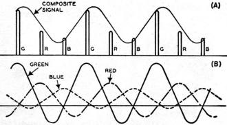
Fig. 6 - Operation of the receiving set sampler system.
Color Fundamentals
To start at the beginning, let us investigate a few facts about color. Color,
physicists tell us, is a property of light. If we take sunlight and pass it through
a glass prism, a variety of colors are produced. White sunlight contains all colors
but, due to the limitations of the human eye and the fact that the colors produced
by the prism blend into each other, we can count only seven fairly distinct colors.
Upon closer inspection of this color distribution, innumerable fine gradations may
be distinguished, both between different colors and within anyone color itself.
For example, red when it first becomes definitely distinguishable from its neighbor,
orange, possesses a different shade than it does at the other end of the red band,
where the infrared wavelengths are approached.
Now all the various shades and tints that are contained in the spectrum can be
reproduced by combinations of three pure colors. The colors are red, green, and
blue and these have been named the "primary" colors. To obtain a certain color,
we combine the primary colors in definite proportions. Yellow may be derived from
combinations of red and green; orange by other proportions of the same two colors;
white by using all three, etc. These facts have been put to use in color television
by breaking down the light received from a scene into its primary components at
the transmitter and then recombining them at the receiver.
RCA System
In the RCA system, the scene to be televised is picked up by a color camera containing
three camera tubes. The light entering the camera is passed through special mirrors
(known technically as dichroic mirrors) which possess the property of being able
to reflect one color but pass all others. Thus, a red dichroic mirror will reflect
red light, but permit all other light to pass through. In the color camera, red
and blue dichroic mirrors are arranged in the manner shown in Fig. 1. The portion
of the incoming light which is red is reflected by the red dichroic mirror (and
a second reflecting mirror) into one camera tube. The blue portion of the incoming
light is reflected into a second camera tube by the blue dichroic mirror (and a
second reflecting mirror). What remains of the light after passage through the two
dichroic mirrors, green, is received by the third camera tube. In this manner every
bit of light reaching the camera is sorted into its primary color components.
The output from each camera is now transferred through separate low-pass filters
(which pass only video signals having frequencies up to two megacycles) to an electronic
sampling tube. See Fig. 3. At the same time this is happening, portions of
the three-color signals from the camera are combined in electronic Adder No.2 and
passed through a bandpass filter where video frequencies up to 2 mc. are suppressed
and those from 2 to 4 mc. are transmitted. This system of dividing the color signals
into separate low- and high-frequency components and then combining all of the high-frequency
components together is known as a mixed-high system. Why this particular method
was chosen will be indicated presently.
The mixed-high frequencies are fed to Adder No.1 which is also receiving signals
from the electronic sampler. However, while the mixed-high frequencies are arriving
in a continuous stream, the low-frequencies are arriving in spurts, from the electronic
sampler, in the form of short pulses. Within the sampler, an electron beam is revolving
at a rate of 3.8 million times per second. The beam thus comes in contact with the
color signal from each camera 3.8 million times in each second providing Adder No.1
with this many samples from each color, one sample arriving every 0.263 microsecond
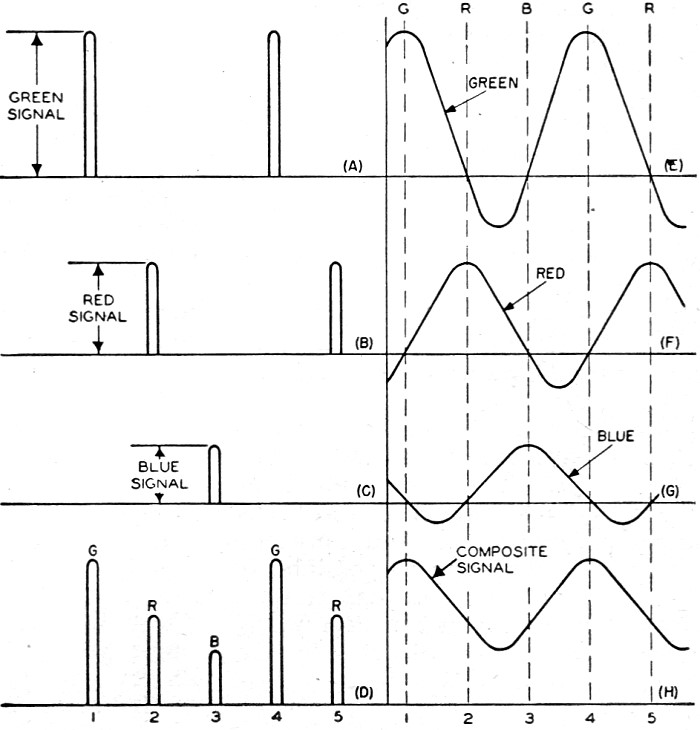
(1/3.8 = 0.263). Fig. 4 shows the output of the sampler for a short period
of time. In Fig. 4A, the output of the sampler for the green signal is shown.
A green sample (pulse of voltage from the signal fed to the sampler by the camera
receiving the green portion of the incoming light) appears every 0.263 microseconds.
At a time 0.0877 microsecond after the first green sample, a sample is taken
of the voltage from the camera receiving the red rays of light. The red samples
themselves, however, are spaced 0.263 microsecond apart. Blue samples are taken
at the same rate as the red and green samples and appear 0.0877 microsecond after
a red pulse of voltage. The composite sequence of these voltage pulses is shown
in Fig. 4D. For any particular scene, the strength of each pulse would depend,
of course, on the amount and shading of the color rays reaching the camera.

Fig. 7 - RCA color TV direct-view picture-reproducing system
using 3 kinescopes and two dichroic mirrors.
The pulses at the output of the sampler tube are fed to Adder No. 1 where they
are combined with the mixed-highs signal. Both signals are applied now to a low-pass
filter (passing 0-4 mc.) where the pulses of voltage from the electronic sampler
are smoothed out. Each of the smoothed out pulses now becomes a sine wave having
a frequency of 3.8 mc. See Fig. 4E, F, and G. It should be noted in these sine
waves that when any one color signal reaches its maximum value, the other two color
signals are passing through zero. This is important and insures that when the signals
are again sampled at the receiver, that only one color is obtained during each sampling.
While the three sine waves are shown separately in Fig. 4E, F, and G, they
are actually combined in the low-pass filter to form the composite signal shown
in Fig. 4H. It is this composite signal which combines with the mixed-highs
signal to provide the complete video signal. The remainder of the transmitter now
follows the usual sequence of amplifying this voltage, impressing it onto an r.f.
carrier and sending it out over the air to the receiver.
Color Television Reception
The color television signal at the receiver (together with the accompanying sound)
is received and amplified by a series of stages which, up to the second detector,
are similar in all respects to the same stages found in present black-and-white
television receivers. Thus, there is an r.f. amplifier, a mixer, a high-frequency
local oscillator, a series of video i.f. stages and a conventional second detector.
See Fig. 5. The same is true of the audio system with its i.f. amplifiers,
discriminator, audio amplifiers, and speaker.
Now, the video signal at the output of the second detector consists of the composite
color signal, as shown previously in Fig. 4H, plus the vertical and horizontal
synchronizing pulses which are required to keep the receiver image in step with
the transmitter image. Part of the signal is applied to a sync separator stage where
the sync pulses are divorced from the rest of the signal and then fed to sawtooth
deflecting circuits where they lock-in the sweep oscillators. This, again, does
not differ from conventional black-and-white television receiver practice.
The rest of the signal from the video second detector is fed to a sampler tube
which is similar to the sampler tube employed at the transmitter. Every 0.0877 microsecond,
the sampler tube samples the composite signal, producing the narrow pulses shown
in Fig. 6A. The amplitude of each sample will depend upon the strength of the
composite wave at that particular instant. This same stipulation was true at the
transmitter, it will be remembered.

Fig. 8 - RCA color television projection picture-reproducing
system using three projection kinescopes, reflective optics, and two dichroic mirrors.
The sampler sends these pulses to each of the video amplifiers and its associated
cathode-ray tube in succession. Thus, looking at Fig. 6A, the green pulse goes
to the video amplifier system which is associated with the cathode-ray tube emitting
green light, the red pulse goes to the red video system, and the blue pulse goes
to the blue video system. The sequence then repeats itself, going from green, to
red, to blue for as long as the equipment is in use. To insure that the sampler
tube sends the series of pulses to the various video amplifiers in proper sequence,
the trailing edge of the horizontal synchronizing pulse is used to drive both receiver
and transmitter sampler tubes.
When the three colored pulses pass through their respective video amplifier systems,
they are smoothed out to the sine wave form shown in Fig. 6B. Note that while
all of the signals are shown together in this illustration, only the green signal
goes to the green cathode-ray tube, only the red signal goes to the red cathode-ray
tube, and only the blue signal goes to the blue cathode-ray tube. The image that
is produced on each cathode-ray tube will thus depend upon how much of the scene
being sent by the transmitter contains that particular color. If, for example, there
is a considerable amount of red detail in the scene, with little blue and say slightly
more green, then the amount of detail visible on each separate image tube will vary
accordingly. The light output of all tubes are combined then to form the complete
picture, to provide the true shading of the original scene.
In the receiver shown in Fig. 5, the total signal consisting of the sampled
signal plus the mixed-highs has been inserted in the receiver sampler and when this
unit samples portions of the incoming signal, it obtains for each pulse the proper
low frequencies for that color plus a combination of the mixed-highs.
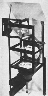
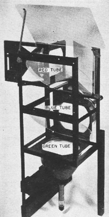
Fig. 9 - Another way of combining the three colored image
tubes.
Consider carefully what happens to the high frequencies. At the transmitter these
high-frequency components of each color were combined, first with each other, and
then with the low-frequency composite signal obtained from the output of the sampler.
At the receiver, when the electronic sampler samples the signal, it will obtain
not only the particular color wanted, say blue, green, or red, but in addition,
it will also receive a combination of the high-frequency components of all three
colors at the same time. Thus, each cathode-ray tube will have its own color plus
essentially the same highs or fine detail. Since each image tube receives the same
amount of fine detail, the combination of these three colors in the final image
will produce either white, black, or intermediate shades of grey. This is because
the combination of the three primary colors, in equal amount, will produce white
or its equivalent. Thus we see that in a "mixed-highs" system, the fine detail of
the image will appear in monochrome, and the larger detail will be in color.
The "mixed-highs" system is similar to the process of color rotogravure used
in printing newspapers and periodicals. To print a color photo, the three primary
colors are used, with the addition of a fourth plate which is black. This fourth
plate adds black, white, and the intermediate shades of grey to the image formed
by the three primary colors. It has been found that through the use of this fourth
plate, the depth, emphasis, and richness of the picture are increased. The same
results are observed in television.
Reception with Black-and-White Receivers
The signal which is radiated by the color transmitter consists of a composite
voltage obtained by combining the low-frequency components of each color with the
mixed-high components. The total signal, therefore, possesses all of the information
needed to develop a black-and-white image with full resolution. When a black-and-white
receiver is tuned to a color broadcast station, the total signal, after the video
second detector, is passed through several video amplifiers and then applied to
a conventional cathode-ray tube. It is true that there is a 3.8 mc. sine wave superimposed
on the picture signal due to the 3.8 mc. sampling frequency at the transmitter.
This will produce a dot pattern on the black-and-white image tube in highly colored
areas, but the dots are not noticeable at normal viewing distances.
When a color receiver is tuned to a television broadcasting station transmitting
a black-and-white signal, the picture will appear in black and white with full resolution
on the color receiver screen. The successive pulses delivered to the three image
tubes will all be of equal magnitude, and, hence, will produce varying intensities
of white - which represents a normal black-and-white picture.
Color Receivers and Color Converters
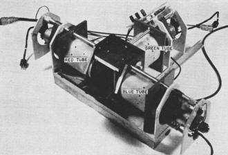
Fig. 10 - Arrangement of projection tubes and their optical system.
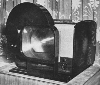
Fig. 11 - A television color converter constructed by CBS.
With a simple adapter built into the set, it enables a black-and-white television
receiver to pick up color broadcasts. The converter is mounted on the front of the
set so that the viewer may have either type of reception by sliding the color attachment
in front or away from screen.
A color receiver requires three image tubes plus some method of combining their
images to produce the single final color picture which is viewed by the observer.
Fig. 7 illustrates one method of combining these tubes using cathode-ray tubes
which are similar electrically to present image tubes except that the phosphorescent
screen of each is designed to produce either a red, green, or blue image. These
images are then viewed through two dichroic mirrors. The red mirror reflects the
light rays streaming from the red cathode-ray tube screen, while permitting the
green and blue rays to pass. The blue dichroic mirror reflects the blue rays, but
permits the green (and all other) rays to pass. An observer, standing in front of
the first mirror, thus sees only the combined color pattern of all three tubes.
Another means of mounting. the three tubes, in order to obtain the final image
by reflection from a silvered mirror, is shown in Fig. 9. Again two dichroic
mirrors are required.
It is not necessary to restrict the tube arrangement to direct-viewing tubes.
Projection systems are also perfectly feasible and Figs. 8 and 10 show the manner
in which the projection beams can be combined to form the final enlarged color image.
The cabinet to house the projection tubes, Fig. 12, is very similar to black-and-white
pro-jection cabinets.
An important feature of this system is its compatibility with television receivers
already on the market. From an examination of Fig. 5 it can be seen that to
convert a current black-and-white receiver to receive color transmission with the
foregoing system requires the addition of color sampling circuits and three color
image tubes. Just how expensive something like this may be is difficult to foretell
at this time since there is a very distinct possibility that a single cathode-ray
tube using three separate guns will take the place of the three color image tubes.
Such a tube has been developed experimentally both in this country and in England,
but has never been manufactured in any quantity.
Two-Color System
It is claimed by RCA that color transmissions can be received with a simplified
receiver using two colors instead of three. The two colors are blue-green and green-red.
A block diagram of a two-color television receiver is shown in Fig. 2. It is
seen to be similar to the diagram of Fig. 5 except that now only two image
tubes and two video amplifier systems are required. The sampling method remains
essentially the same, although the times when samples are taken of the composite
wave is altered.
In Fig. 4, the sine waves due to each of the color pulses are shown separately,
together with the composite signal. At time 1, the green sine wave is at a maximum
and the other two color signals are passing through zero. Hence, if the receiver
sampler takes a sample of the composite wave at this instant, it will obtain a pulse
of voltage which is governed only by the green signal. This pulse, if the system
is operating properly, will go into the video amplifiers feeding the green image
tube.
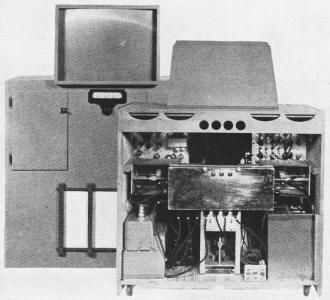
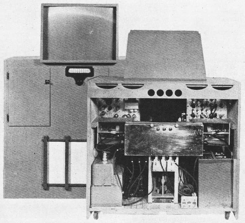
Fig. 12 - Front and rear views of RCA color projection receiver.
Image is 15" x 20".
By the same reasoning, a pulse sample taken at time 2 will represent the red
signal and a pulse sample at time 3 will represent the blue signal. At time 4, the
sequence starts over again.
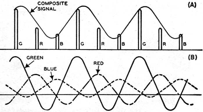
For the two-color television receiver, the same signals as in Fig. 4 are
shown in Fig. 13; however, the instants when samples are taken have now been
altered. The composite signal is sampled for blue-green at a time when both blue
and green are in a positive direction. This is indicated by the line marked B-G.
Similarly, the composite signal is sampled for green-red at a time when both of
these components are in a positive direction. This is indicated by the line marked
G-R. No sample is taken at the third point.
The two samples are fed to separate video amplifiers and cathode-ray tubes and
the final image is formed by combining the light output of both screens. A color
converter using a two-color picture-reproducing system is shown in Fig. 14.
To keep the cost of this color converter as low as possible, the black-and-white
image tube already in the receiver is used with a suitable filter placed in front
of it. All we require then is a sampling circuit and a second image tube and a suitable
dichroic mirror. If the two-color system is to be used for an inexpensive color
television receiver, the two image tubes would possess the proper color phosphors
and filters would not be needed.
The CBS System
The CBS color system has been labeled by many as a "mechanical" system but CBS
claims this is not actually so. True, up to now, in nearly all tests run with the
equipment, mechanical scanning filters have been used - but the mechanical components
could be replaced by electronic methods both at the transmitter and the receiver.
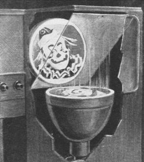
Fig. 14 - Two-color picture-reproducing system.
At the studio camera, a rotating color disc is placed in front of an Image Orthicon
camera tube. See Fig. 15. The color disc contains the three primary filters,
red, blue, and green arranged so that there are four groups of these three primary
colors, or a total of 12 filter segments. The light from the televised scene must
pass through one of these filter segments to reach the camera tube and in so doing
loses all color components except the one which matches the color of the filter.
The speed of the disc is synchronized with the action of the electron beam within
the camera tube so that one field is scanned while a filter segment is passing in
front of the camera tube.
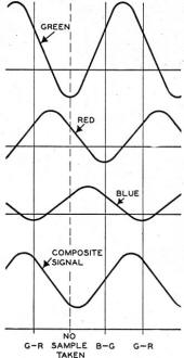
Fig. 13 - Operation of the receiver sampler in a two-color
system.
To illustrate, suppose that at any one instant the red filter is in front of
the camera tube. During this time, the red filter is permitting only light from
the red-colored sections of the scene to reach the mosaic of the tube. With the
red filter in position, the electron beam scans the mosaic and the electrical pulses
corresponding to the red-colored sections of the scene are formed and transmitted
through the video amplifiers. The filter in front of the camera tube remains in
this position throughout the entire scanning run (one field of either the odd or
even lines) of the electron beam. The same sequence is followed as each of the other
filters moves in front of the camera tube. The electrical pulses from each of these
scannings follow each other in succession through the various transmitter amplifiers.
At the receiver (Fig. 16) the pulses arrive in the same order in which they
were transmitted. As they are traced out on an ordinary cathode-ray tube screen,
the corresponding colored filter should be in position in front of the viewing screen.
The observer, in viewing the image through the rotating filter, sees these colors
as they appeared when they entered the camera tube. The lines are traced so rapidly
that each individual color sequence blends into the next, and only the completed
image appears to be present. This is similar to the action with ordinary television
images. Here, too, the even and odd lines are scanned separately, but the observer
integrates them both in his mind to form the resultant complete image.
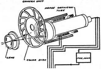
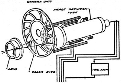
Fig. 15 - In the CBS color system, the incoming light rays
are filtered by a color disc before reaching the camera tube.
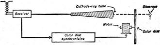
Fig. 16 - Block diagram of CBS color unit.
To insure that the color disc at the receiver is in step with the color disc
at the transmitter, a special synchronizing pulse is incorporated into the video
signal.
It is possible to replace the rotating color disc and the single black-and-white
cathode-ray tube at the receiver by an all electronic viewing system consisting
of three separately colored image tubes. The incoming signals would then be routed
by a special cir-cuit to the proper image tube and the final image would be formed
by superimposing the light output of each tube. This is similar to the RCA system.
It is, however, admittedly more economical to utilize the mechanical scanning disc.
The CBS color system, as currently constituted, occupies a 4.5 mc. bandwidth,
uses 405 lines (as against 525 lines in the present black-and-white system), and
144 fields per second. With these standards the number of picture elements along
each line is 45% less than in standard black-and-white pictures. CBS claims that
with normal program material, the loss in detail is not too noticeable.
Thus, we have here the two major systems competing with each other before the
FCC. The RCA system is essentially a dot sequential system while the CBS is field
sequential. Demonstrations are being conducted by both organizations (along with
others) at the hearings with the avowed purpose of attempting to bring to a head
the controversy and possibly enable the FCC to come to a definite conclusion concerning
the feasibility of either system (or possibly some other system, of which several
have been advanced) and establish a set of standards. It is even possible that the
FCC will feel that none of the systems thus far advanced are suitable and refrain
from making any decision at this time, preferring to delay the introduction of color
television until more experimental data is available. In any event, the choice,
or lack of it, is expected to be definitely announced within the next few months.
Color and Monochrome (B&W) Television
Articles
Posted March 30, 2023
(updated from original post
on 1/6/2017)
|