|
If the technology futurists
of the 1970s had been correct, by now we would be reading historical articles on
the early days of holographic television. I have read, though, that any day now
a battery-powered flying car with a holographic dashboard / instrument panel display
is going on sale. Not. The Sadly, the
Ercoupe (pronounced
"air coupe," as in automobile coupe of the air) is still the closest thing to "an airplane in
every garage." But, I digress. This story from a 1953 issue of Radio & Television
News magazine reports on the roll-out of the country's first color television
system: The field sequential system (aka the CBS system). It was a fine system,
but unfortunately the modulated signal format was not backward compatible with the
existing black and white (B&W) system. That meant separate receivers for B&W
and color televisions. Even as CBS TV sets were being produced, the
National Television System
Committee (NTSC) was working on a replacement system that permits co-existence
of B&W and color signals. Note the mention of how the DPA (Defense
Production Administrator), in 1951, requested that color TV manufacturers halt
research and development on the CBS system in order to free engineers for defense-related
design and production hardware, it being the death knell of CBS and clearing the
way for NTSC (Korean
War).
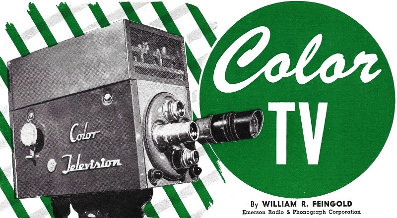
Color TV - Part 1: Clarifying the color TV situation with some
predictions on what to expect in color receivers.
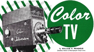
Fig. 1. An experimental single-tube color TV camera, not
much larger than its black-and-white counterpart.
By William R. Feingold,
Emerson Radio & Phonograph Corporation
On October 11, 1950, the Federal Communications Commission approved the field
sequential system (popularly known as the CBS system) as the official color TV standard
for the United States. This system had been under development for approximately
10 years, and gave a fairly presentable performance in comparison with competitive
methods which were more or less newly conceived. It was an unfortunate choice, however,
because the field sequential color system required a vertical field rate of 144
per second (as opposed to the black and white of 60) and a line rate of 29,160 cycles-per-second
(as against the black and white of 15,750) to eliminate flicker, thereby making
this system incompatible with black and white transmission standards. Finally, when
the DPA terminated all color TV activity on November 20, 1951 in the interest of
national defense, the CBS system, as used in aerial TV transmissions, died a natural
death. For strictly industrial television use, the CBS system is still being employed
in closed circuit applications.
In the meantime, the Radio-Electronics-Television Manufacturers Association set
up a committee to formulate an improved compatible color signal. The more than 200
engineers and physicists of this National Television System Committee (NTSC) from
91 leading companies in the television industry formulated and tested a color TV
signal which could fit into the present 6 mc. channel, and was compatible with the
black and white transmission standards.
The NTSC does not own any equipment, neither transmitters nor receivers, and
is not interested in the detailed circuitry of either type of equipment. Its interest
in equipment stops at the point where it has been established that the signal specifications
can be met with readily available gear. The end goal is a set of signal specifications,
proven and practical, that can be presented to the FCC for approval. That this goal
has been met has been amply attested to by the fact that numerous organized field
tests have been arranged by the NTSC and attended by some 15 different manufacturers
with their color receivers. These receivers represent the varied outputs of the
different engineers all working from the same signal specifications and all receivers
are producing excellent pictures.
The NTSC Signal
Although a detailed treatment of this new color signal will be made in the second
article of this series, a simplified treatment is in order.
From a welter of data pertaining to the physiological aspects of color vision
and a mass of theoretical data regarding the character of the television signal
itself, the following color signal has been formulated. To the present monochrome
standards as they now exist an additional color signal specification has been added.
The resultant effect is not unlike the conventional lithographic technique of printing
in three colors plus black to add the detail. In our case, the present monochrome
information carries the shades of black and white including all the fine detail,
and the color information is added on a color sub carrier to fill in the large areas
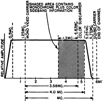
of color (Fig. 2).
Tests have shown that the eye cannot perceive fine color detail, hence, there
is no need to burden the color circuits with wide-band information. The shaded area
on Fig. 2 indicates that this color information in the lower sideband is restricted
to a bandwidth of 1.3 mc. Note, too, that the upper sideband cannot extend this
far since the limits of the channel restrict this area to approximately 0.4 mc.
Although this unsymmetrical distribution of sideband energy is not a desirable situation,
it has been possible to design the details of the system in such a manner that it
causes no extra trouble.

Fig. 2. Color signal characteristics.
Because the lower sideband of the color information falls well within the monochrome
video channel it was necessary, in the interest of compatibility, that this color
data be made invisible on a standard black and white receiver. This was done (within
the limitations of the linearity of the system) by setting the color subcarrier
at a frequency which is an odd multiple of half the line repetition rate. The actual
frequency selected by the NTSC is 3.58 mc. This unique feature of adding narrow-band
color information on a special color subcarrier to a standard monochrome transmission
is the essential characteristic of the signal. When a color signal is transmitted,
the conventional monochrome receiver will present the picture in shades of black,
gray, and white with a negligible trace of the picture's color signal origin. An
interesting point is that these black and white pictures usually have better resolution
than that obtained from conventional monochrome reception. The reason for this improvement
is simply that the transmitters have to be more carefully adjusted to handle the
color data on the 3.58 mc. subcarrier and, as a result, the monochrome information
is present in more detail.
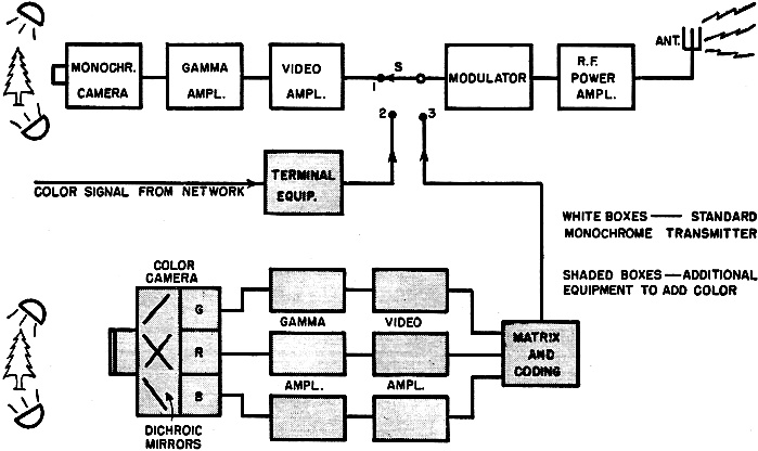
The conversion of a good monochrome transmitter from black and white to color
is simplicity itself. (See Fig. 3.) If a color video signal is already available,
either from a color camera or a network link, no changes are required. To get this
video information from a network a minor investment in new terminal equipment will
be required. Networks will probably be the main source of nationwide color transmissions
until a sufficient number of color studios are constructed.
The color studio gear and the camera equipment are somewhat more complicated
than their monochrome counterparts. Present color cameras consist of three pickup
tubes mounted side by side with each one masked with a proper primary filter. By
the use of properly positioned dichroic mirrors (mirrors which reflect light of
one color and pass all other colors) the single viewed image of one lens is made
to fall on each of the three photosensitive camera surfaces. Since these images
must pass through green, red, and blue filters respectively before they strike these
surfaces, the three resultant video outputs. represent the green, red, and blue
signals corresponding to these colors in the original scene.
Progress has already been made toward the development of a single camera pickup
tube that will put out three primary signals (Fig. 1). There is no doubt that
technical advances in studio equipment will be made towards simplification. In this
connec-tion it is interesting to note that the compatible nature of the signal allows
for testing transmitting and receiving equipment by radiating color signals (with
FCC approval) without public announcements of the fact. One of the first such "sneak"
transmissions took place late in June in New York City on WNBT during a "Howdy Doody"
program.
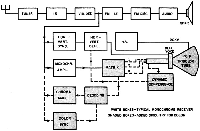
The Color Receiver
The color receiver is basically a monochrome receiver with additional circuitry.
This additional circuitry falls into two groups. The first group is that part required
by the color information alone. In Fig. 4 this area is covered by the chroma,
decoding. color sync, and matrix networks. This part produces as its end product
the green, red, and blue video signals. The second group is that area of circuitry
dictated by the requirements of the picture tube (or display device). Since Fig. 4
indicates an RCA tri-color tube, a dynamic convergence network is used, as required
by this tube.
Although the interior of the color receiver is somewhat more complex than its
monochrome brother, the user's controls are only complicated by the addition of
one more knob. This control is marked "Chroma." It allows a customer who takes issue
with the mathematically correct ratio of color to monochrome to vary this ratio.
The picture color can thus be varied from a light pastel shading to an intense lush
overly-colored display.
With regard to the fine tuning control, the public will have to be reeducated.
It will be recalled that split-sound receivers of five years ago required a careful
setting of the fine tuning control or there was no sound. This careful setting of
the tuner oscillator made for optimum picture quality. However, the problem of oscillator
drift gave way to the use of intercarrier systems with the net result that sound
was always present and tuning the oscillator to obtain the best picture became a
forgotten operation.
In order that the color receiver retain the benefits of intercarrier operation
and yet force the customer to adjust the tuner oscillator to its proper place to
insure good color quality, the designer is forced to use some sort of tuning indicator.
In this case what could be better than the face of the picture tube? The sound traps
in the receiver are made sharp and deep so that when the oscillator is properly
tuned the picture is clean. When the oscillator is mistuned the picture will show
annoying sound patterns.
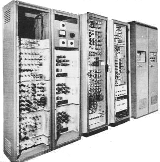
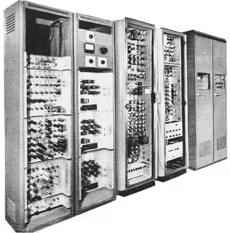
Color TV signal generating equipment used by Emerson for the
design and testing of color TV receivers. Included is a monoscope and flying-spot
scanner.
The most publicized aspect of the color TV receiver has been the picture tube.
All color tubes presently used or being developed have three color phosphors deposited
on the front face of the picture tube in either a dot pattern array or a striped
pattern, horizontal or vertical. The RCA tri-color tube" utilizing three gun structures
is typical of the former type, while the Lawrence tubes as made by Chromatic Laboratories,
containing a single gun, is typical of the latter.
The RCA picture tube contains a phosphor dot pattern consisting of 195,000 dots
in each of three colors for a total of 585,000 dots. The three guns are so arranged
that each gun will excite only its particular phosphor color. As a consequence it
is possible and desirable to excite the three guns simultaneously with their respective
color signals and thereby have a simultaneous light output in red, green, and blue.
This design does not require any form of sequential color switching and provides
a maximum light output roughly three times that which would be available on any
sequential system using this tube. The use of three guns carries with it some severe
mechanical and electronic circuit requirements. The first is the specification that
each gun strike its respective phosphor without contamination from the other two.
The second is the problem of registration of the three colored pictures. Improvements
in the production control of the picture tube and in the electronic circuitry associated
with the tube have reduced both problems to an acceptable level.
The Lawrence tube contains a series of red, green, and blue stripes approximately
0.015 inch wide with a built-in switching grid to allow the single electron beam
to scan anyone color depending on the switching potential present. Because of the
single gun construction, a sequential display is essential. This means that this
tube cannot suffer from any registration problems. However, it does suffer from
a light output loss of two-thirds because only one phosphor is in use at one time.
There is the additional requirement of substantial switching energy to the switching
electrodes.
The test receivers used by the various manufacturers during NTSC field trials
have utilized the RCA tri-color tube exclusively. Although limited numbers of the
Lawrence tube have been released to the industry, a comparative appraisal is not
possible at this time. It is probable that the first production color receivers
will contain the RCA tube.
It should be quite obvious by now that the color receiver will be somewhat more
complex and considerably more expensive than the present monochrome receiver. The
picture tube alone is expected to cost from 150 to 200 dollars. The tube complement
of the receiver will fall between 40 and 50 tubes. These two factors alone make
a cost estimate of the first color receivers fall in the $750 to $1000 class. In
addition, these receivers will produce a small picture, judged by present-day standards.
The most successful RCA tri-color tube developed to date contains an exterior shell
similar to the old 16AP4 and produces a 12 1/2" pumpkin-type picture. Although intensive
developmental work is now going on toward a 16" picture there is no indication when
this larger tube will be available or how much it will cost.
Receiver Production

Fig. 3. Simplified block diagram of a typical color television
transmitter.

Fig. 4. Simplified block diagram of a typical color television
receiver.
Obviously there will be no rush to buy the first color receivers. Very few prospective
customers will buy a 12 1/2" color picture at $800 in preference to a 21" monochrome
picture at $300. However, the novelty is expected to appeal to some, and first production
schedules will cater to this rather meager demand.
How soon manufacturers will put color receivers in the field, after FCC approval,
is entirely up to the manufacturer himself. There will probably not be a repeat
of the 630TS experience where RCA released complete data on this black and white
receiver to their licensees, covering chassis layout, component specifications,
alignment procedure, troubleshooting, etc. It will be necessary for each manufacturer
to build up a nucleus of engineers familiar with the color TV problem. Fortunately,
a number of companies have already done this and have also accumulated a fair amount
of specialized test and alignment equipment.
The next step, however, is actual production. The single bottleneck here is the
test and alignment equipment for line use. Delivery of this material, from only
a few sources, is quoted at from six months to a year. Realizing this, some manufacturers
have already placed orders for production test equipment prior to FCC approval.
Assuming FCC approval early in 1954, it is safe to say that the first color receiver
will be released in the late spring of 1954 with a number of manufacturers in the
field by the fall.
The Service Technician
The conscientious service technician who understands the workings of a black
and white receiver will not fear the complexities of a color receiver. The transition
is not as dramatic as his previous transition from a 5-tube radio to a 25-tube TV
receiver. The additional 15 to 25 tubes required by a color receiver are, in some
circuits, just more of the same. However, in other circuits there are new concepts,
an understanding of which is essential to the proper diagnosis of trouble. At the
present stage of color receiver development, color adjustments are extremely critical,
requiring a broad knowledge of color circuitry. Service technicians will have to
study such circuits conscientiously to be successful in this field.
At this point the writer would like to utter a small prayer on the service technician's
behalf. Knowing that more service test and alignment equipment will be required
in working with a color receiver let us hope that the designers of this test gear
(it has not yet been designed) will keep down the size and weight. In the same breath
let us pray that the designers of these new color receivers allow for troubleshooting
in the home and in the cabinet. These larger chassis are considerably heavier than
black and white chassis with half their tube complement. A combination of lighter
test gear and a chassis which could be "troubleshot" in the cabinet will make for
fewer ruptured service technicians, fewer chassis dropped down the stairs, and what
is not a negligible factor in service technician-customer relations, smaller service
bills.
This article has attempted to dispel the fog that has shrouded the color TV picture.
Considerable progress has been made in the formulation of an improved compatible
color signal. Two applications for a "Change of Rule" have been filed with the FCC.
The first was made on June 25, 1953 by RCA, and the second by the NTSC one month
later on July 23, 1953. In each case a request was made to have the present monochrome
standards amended to provide for color TV transmissions in accordance with the new
NTSC signal. FCC approval is expected by the first of the year or shortly thereafter.
Receiver production should start slowly in the fall of 1954 with a price range
of $750 to $1000. This price range is expected to fall as developmental work continues.
One laboratory has already produced an experimental receiver which requires. only
34 tubes.
Part 2 of this series will discuss the color signal in detail and examine a typical
color receiver.
References
1. Buchsbaum, Walter H.: "The RCA Tri-color Tube," Radio & Television News,
November 1951.
2. Dressler, Robert,: "The PDF Chromatron - A Single or Multi-Gun Tri-Color Cathode-Ray
Tube," Proceedings of the IRE, July 1953.
(To be continued)
Posted August 14, 2023
(updated from original
post on 12/3/2018)
Color and Monochrome (B&W) Television
Articles
|


