|
September 1957 Radio & TV News
 [Table
of Contents] [Table
of Contents]
Wax nostalgic about and learn from the history of early
electronics. See articles from
Radio & Television News, published 1919-1959. All copyrights hereby
acknowledged.
|
The main purpose for bothering
to reprint articles like this one on analog color TV theory is to reveal the complexity
and ingenuity that went into cramming a lot of information into a relatively (at
the time) small bandwidth. Signals within signals and signals riding on top of and
below other signals was the name of the game, and pulling it off successfully required
many well-designed and well-aligned circuits. Anyone old enough to remember watching
a show on analog television can appreciate the difference between a high quality
set with self-adjusting capability and a cheap set that required constant fiddling
with the tiny, fluted knobs on the back. I, by the way, always had (and still have)
the cheap sets. A bad picture on today's digital displays consists of screwy color
tones or a few missing pixels, but at least you can stand to watch your movie or
ball game. If an analog set started acting up, the picture could creep to the top
or bottom of the screen, the horizontal and/or vertical scan synchronizations could
scramble the picture into an indiscernible mess, multipath combined with a poor
receiver could cause ghost images, along with many other annoying phenomena. Proof
of improvement is that instances of having a foot put through a TV screen nowadays
is vastly more likely due to a poor performance on the part of a sports team than
to a crappy picture.
Practical Color TV for the Technician
 By Ken Kleidon By Ken Kleidon
National Color TV Manager Hycon Electronics
Part 2. What service practitioners should know about the components of the color
video signal.
There are four areas of information, as stated in the preceding article, with
which the service technician must become familiar if he is to service color receivers
successfully. These areas cover all aspects of the transmitted color signal, the
special color circuits used in the receiver, the new type of picture tube used at
the receiving end, and the special service techniques and procedures required. This
article will be primarily concerned with the signal.
Because of the compatibility requirement, a monochrome receiver must be capable
of receiving a color transmission and of reproducing directly from it a picture
in black-and-white without modifications or additions to that receiver. To facilitate
this requirement, the same transmission standards imposed on monochrome signals
apply equally to color signals. The latter must contain, at least, all the information
provided by a black-and-white broadcast and the same specifications must apply,
including the 6-mc. bandwidth for the channel, placement of the sound carrier at
4.5 mc. above the picture carrier, and so on.
When the transmitted monochrome signal is analyzed from the standpoint of the
service technician, it is found to consist of three component signals - one relating
to video information, another to sound information, and a third to synchronizing
information. A color transmission must carry each of these, but it also includes
separate, additional information relating to color. Since this added intelligence
must be contained within the same 6-mc. bandwidth that is allotted to the monochrome
transmission, this color-signal content has been devised in such a way that it will
not interact or interfere with the monochrome signal and that it will not affect
operation of the circuits in a receiver designed for black-and-white reception only.
As a result of this seemingly odd relationship between these separate but related
monochrome and color signals, the manner in which a color TV picture is processed
and reproduced in the receiver is quite distinctive. First the monochrome signals
are processed by circuits similar to those in conventional monochrome receivers
to produce a black-and-white picture. Then the color signals are separately processed
by additional circuits especially designed to respond to them. The resultant color-producing
information is then superimposed over the monochrome picture to produce an image
in color.
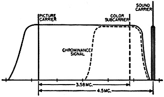
Fig. 1 - Chrominance signal (broken line) squeezes into
channel bandwidth.
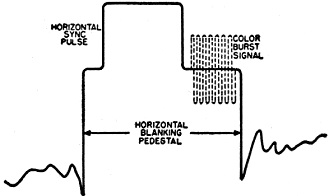
Fig. 2 - Color burst (broken line) is added to horizontal
pulse's back porch.
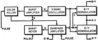
Fig. 3 - Expansion of block in Fig. 4 labeled "color
circuits." This is one system in popular use, but others exist.
TThat this manner of producing the end result is indeed used can be demonstrated
in a practical way without going into technical details, if a properly adjusted
color receiver is tuned to a color TV broadcast. If the color (or chroma) control
is rotated to its minimum position, a black-and-white picture results. This is what
has happened: turning down the chroma control has had the effect of discontinuing
operation of the special color-processing circuits, or at least of preventing their
output signals from reaching the picture tube. The separate monochrome circuits
continue to operate, however, and a black-and-white picture results.
A practical analysis of the transmitted color signal reveals that it includes
five components. Three of these - video, sound, and sync - are identical to those
found in monochrome transmissions. The other two are incorporated to permit the
addition of color. Since the sound, signal is virtually a separate transmission
on a separate, although related, frequency and since it is not affected by the fact
that we are dealing with either a monochrome or color broadcast, we can put it aside.
The video (or brightness, or luminance) information, which provides variations in
light or dark, is interwoven with the sync signal in standard monochrome practice.
The purpose of the latter signal is simply to make sure that the variations in light
occur in the right places on the screen of the receiver.
In dealing with color information, we have a somewhat similar situation: the
chrominance signal, one of the two new components in the transmission, carries variations
in color; while the color-burst or color-synchronizing information, the second of
the two added signals, helps the receiver establish and separate the colors from
the chrominance information provided, and makes certain that the right colors are
being fed to the picture tube at the right time and in the right places.
With the help of Fig. 1, we can see how the chrominance signal is squeezed
into the limited bandwidth available Actually it co-exists with already present
video information occurring at the same frequencies. Everything that appears in
solid line pertains to the signals with which we are already familiar in the case
of monochrome transmissions. A color subcarrier at 3.579545 mc., usually referred
to as 3.58 mc. for convenience, is shown in broken line. The extent of its modulation
sidebands are also shown in broken line.
Actually, in order to describe a full range of color variations electronically,
we need two signals, not one. If both of these can be varied over a wide range,
and the final color produced is the result of the combination of these two, then
we have an almost infinite range of possible combinations. This gives us a wide
potential for representing different hues (red, green, blue, etc.) and different
degrees of color intensity, or saturation.
Since the limited bandwidth available for any channel makes it difficult enough
to squeeze in even one additional carrier (at 3.58 mc.) , both of the signals required
for chrominance information are ingeniously modulated onto this single carrier in
such a way that they do not interfere with each other. It is as though two subcarriers
at exactly 3.58 mc. were used. One, however, although it is at exactly the same
frequency, is 90 degrees out-of-phase with the first. Hence, these two are said
to be in quadrature. In this way, if we can adjust circuits in the receiver to be
sensitive to the difference in phase between these two signals, we can have the
effect of separate signals in the set.
Since these chrominance signals are added in the form of amplitude modulation
and since the 3.58-mc. frequency at which they occur falls within the 4-mc. bandwidth
within which black-and-white video information also occurs, we have an additional
problem. Because the receiver's video detector is designed to respond to amplitude
modulation at this frequency, the color-carrying 3.58-mc. signal will show up as
a rather fine-grained beat interference, marring the monochrome picture. To avoid
this, the subcarrier that has been so carefully devised to provide us with desired
additional information is filtered out and discarded at the transmitter! Its effect
is not lost however: its modulation sidebands continue to be transmitted; and provision
is made for reinserting the carrier in the receiver itself, safely away from the
monochrome circuitry, so that it may once again be presented effectively with its
sidebands. In a conventional black-and-white set, of course, no such reinsertion
is made.
The second new element added to the transmitted signal for use by color-receiver
circuits is shown in Fig. 2. In solid line, we see the familiar horizontal
blanking and synchronizing pulse, with video (luminance) signal visible just to
either side of it. Inserted on the back porch of this pulse are 8 cycles of sine-wave
signal at exactly 3.58 mc., as indicated by the broken lines. Although this color-burst
signal, as it is known, has no noticeable effect on the operation of the sync and
deflection circuits, it is picked up by certain added circuits in the color set
that make important use of it.
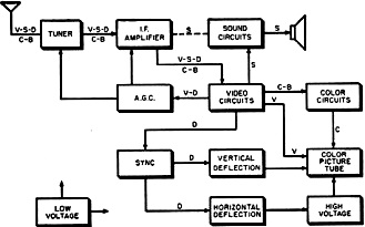
Fig. 4 - In this block diagram of a color TV receiver, the
five basic components of the signal transmitted (identified in text) are shown in
the various paths they follow through various receiver circuits. Except for the
color block, note basic similarity to monochrome circuitry.
It is principally used to synchronize a subcarrier reference oscillator built
into color sets, tuned to 3.58 mc., in a manner that may be compared to that in
which the 15,750-cps pulse is used to synchronize the horizontal oscillator in all
TV receivers. In this way, the transmitter tightly controls the receiver's reference
oscillator in phase as well as frequency. Thus the reference oscillator provides
a reliable substitute for the sub carrier that has been filtered out at the transmitter
and permits establishing the accurate phase relationship that is necessary to distinguish
between the two quadrature signals that make up the chrominance information.
At this point we would do well to summarize our knowledge of the signal. The
monochrome transmission has three separate components, relating to video, sound,
and sync. Two more are added, for a total of five, to make up the complete compatible
color signal. One of these, the chrominance signal, can be regarded as the color
video signal. The other, the color burst, is another sync solely for use by the
special color circuits. It is used to synchronize a 3.58-mc. reference oscillator
in much the same way as the horizontal sync pulse is used to control the horizontal
oscillator.
If we follow the course of these signals inside of a color receiver, we note
that all five of them - the video (V), the sound (S), the sync or deflection (D),
the chrominance (C), and the color burst (B) - enter the antenna and proceed through
the tuner and i.f. amplifier stages together, as shown in Fig. 4. From this
portion of the set, the 4.5-mc. sound i.f. carrier may be separated and sent directly
on to the conventional sound circuits.
The remaining signals go to the video circuits (detector and video amplifier).
The sync or deflection signal is taken off for feeding to the sync circuits, which
operate the horizontal and vertical oscillators. In addition, sync pulses are generally
used to operate the keyed-a.g.c. circuits found in color sets. Video information
is amplified and supplied to the picture tube. The color-burst and chrominance signals
are applied to and processed by the color circuits. The resulting color video information
is applied to the picture tube, where it is added to the existing monochrome image.
The same system for processing color intelligence is not used in all receivers.
However, as a starting point, the block marked "color circuits" in Fig. 4 has
been separately expanded in Fig. 3 to correspond to one of the popularly used
color systems.
Since the color burst occurs during horizontal sync-pulse time, many circuits
in the color-processing section take the pulse, in one form or another. It is applied,
for various purposes, to the color killer, the burst keyer, and the bandpass amplifier.
Also applied to the latter section are the chrominance signal and the color burst.
After amplification, the burst is separated by the keyer, applied to the burst amplifier,
and then fed to the 3.58-mc. color-reference sub carrier oscillator. Here it performs
its important function of synchronizing that oscillator.
The chrominance signal, after leaving the bandpass amplifier, is passed on to
the two color-signal demodulators. In this receiver, they are the B-Y and G-Y demodulators.
Y stands for the black-and-white (or luminance or brightness) component. B, G, and
R stand for the three primary colors, blue, green, and red, used in color television,
from which all other colors and color combinations are made. B-Y, then, would stand
for all blue signal information minus the information concerning its brightness,
or the amount of black or white with which it is mixed. (The latter, of course,
is inserted separately by the monochrome that is supplied and which is then "painted
over" with the appropriate colors.) Similarly, G-Y and R-Y stand for the green-only
and red-only information.
After the B-Y and G-Y (or blue and green) information has been removed from the
total chrominance information found in the transmitted signal, it is possible to
develop the R-Y signal from what remains without resort to a separate demodulator.
These three color-difference signals, as they are called, are subsequently applied
to the three guns in the picture tube.
Much detailed information concerning the exact nature of the color signals has
been left out deliberately. It is hoped that enough information has been covered,
however, to give a broad understanding of what these signals are and to assist in
understanding receiver function with respect to them.
(To be continued)
Posted January 12, 2023
(updated from original
post on 9/23/2014)
Color and Monochrome (B&W) Television
Articles
|