This was a multi-part series published
by Radio & Television News magazine in the days when color TV was the
domain of the more well-to-do folks on the block. Needless to say (but I'll say
it anyway), nobody I knew had color TV before around 1968. One of my friend's father
owned a fairly profitable gas station and service garage, so they were the first
to have one. For some inexplicable reason (I jest), his mother never allowed more
than one or two of us into the house at a time, so we drew straws to see who got
to witness that fabled miracle of technology. I was about third in line. Insomuch
as the 1960s were a much more polite and private time than the present, peeking
through a living room window for a preview was
 expressly verboten. In fact, going into a
friend's house for any reason was rare. The privileged appointments were strictly
adhered to and monitored by my friend's mother. After a seeming eternity of days,
it was finally my turn to watch color television. The Flintstones were on that particular
afternoon. Discovering that Wilma had red hair was unexpected enough, but a purple
Dino the dinosaur nearly rocked me back on my 10-year-old heels. Of what other essential
details in the age of 'Living Color' had I been deprived, I wondered? expressly verboten. In fact, going into a
friend's house for any reason was rare. The privileged appointments were strictly
adhered to and monitored by my friend's mother. After a seeming eternity of days,
it was finally my turn to watch color television. The Flintstones were on that particular
afternoon. Discovering that Wilma had red hair was unexpected enough, but a purple
Dino the dinosaur nearly rocked me back on my 10-year-old heels. Of what other essential
details in the age of 'Living Color' had I been deprived, I wondered?Fundamentals of Color TV
Tri-Gun Receiver CircuitsBy Milton S. Kiver
President, Television Communications Institute
Part 4. Tuner, video i.f., video amplifier, and sound circuits of typical color
TV sets described in detail.
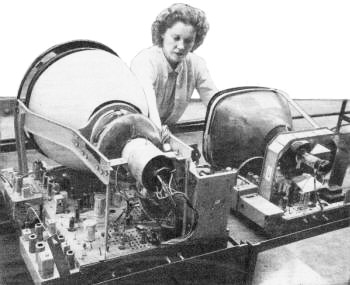
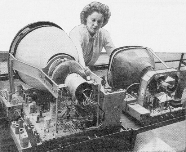
Comparing production model 3-gun, 15" color TV set with black-and-white
17" set. Color receiver uses over twice as many components.
In last month's article we examined in some detail the block diagram of a color
television receiver designed to operate with a tri-gun color picture tube. Now we
are ready to consider the actual circuits which each of the blocks represented.
R.F. Tuner. The introduction of color in no way alters or modifies the r.f. section
of the television receiver. Thus, the r.f. amplifier should still possess high gain
and low noise; the oscillator still provides a signal which, when mixed with the
incoming signal, will produce the desired difference or video i.f. frequencies.
For the reception of v.h.f. signals, either a turret tuner or a continuous arrangement
is employed. For u.h.f. reception, continuous tuning is the most common method although
there is also avail-able an 82-channel turret tuner.
A typical v.h.f. turret tuner circuit is shown in Fig. 1. Cascode amplifiers
are common in the r.f. stage, although some manufacturers favor single high-frequency
miniature pentodes. The oscillator tube is invariably a triode, usually half of
the mixer tube. The latter may be another triode (i.e., 1/2 of a 6J6) or pentode
(1/2 of a 6U8). This arrangement requires only two tubes for the entire tuner section.
In the tuner shown in Fig. 1, the cascode r.f. amplifier uses a 6BZ7 duo-triode.
One section of a 6J6 serves as the mixer while the other section functions as the
oscillator. Balanced 300-ohm and unbalanced 75-ohm (coaxial line) input impedances
are provided by a center-tapped primary winding, L101A. All signals must
pass through a high-pass filter designed to attenuate all signals below channel
2.
The secondary winding, L101B, is tuned by the input capacity (of the
first triode unit) in series with alignment trimmer C105 Loading of L101B
by R101 provides the required bandpass, particularly on the lower v.h.f.
channels. The a.g.c. bias is applied to the first triode of V101 through
decoupling resistor R102.
Direct coupling is used between the first triode plate and the second triode
cathode. This is normal in cascode circuits. With cathode feed to the second triode,
C103 is used to place the grid at r.f. ground potential. Since the two
triode sections of V101 are in series across a common plate supply, the
cathode of the second triode is positive with respect to chassis ground. A divider
across the "B+," consisting of R103 and R111, places the grid
of the second triode at a sufficiently positive potential (with respect to its cathode)
for proper operating bias.
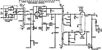
Fig. 1 - Typical r.f. tuner used with color TV receiver.
This is a turret-type unit for v.h.f. only, however combination v.h.f., u.h.f, models
are also used.

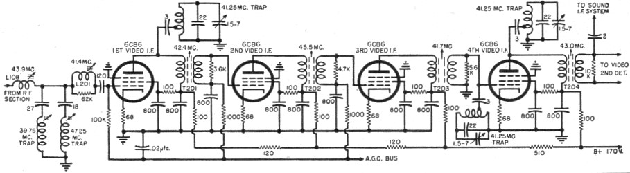
Fig. 2 - The video i.f.
circuits of one color TV receiver. Four stages are used here 10 assure a wider and
more uniform bandpass than for black-and-white sets.
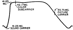
Fig. 3 - Video i.f. response curve of a color TV receiver.
Note the steep slope of the curve between 41.25 and 41.65 mc.

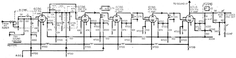
Fig. 4 - Five stage video i.f. system employed by RCA
in its color TV sets.
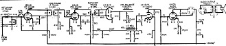
Fig. 5 - Sound i.f. and audio circuits of a typical
color television receiver.
The signal at the plate of the second triode of V101 is inductively
coupled into the grid circuit of the mixer. At the same time, a voltage from the
oscillator is similarly brought into the mixer circuit. The mixer combines both
signals to produce the desired i.f. and then transfers this signal to the following
i.f, stages.
The oscillator is of the ultraudion variety with a front panel fine-tuning control.
Video I.F. Section. The video i.f. system follows the r.f. tuner. This will consist,
usually, of four and sometimes five separate stages. See Fig. 2. In the conventional
black-and-white television receiver, three i.f, stages was the number most frequently
used, although four stages were found in some sets. The increased number of i.f,
stages in a color receiver stems, in part, from the wider bandpass required (4.2
mc.) and from the greater precautions that must be taken to insure that the response
curve will possess the right form.
The desired response curve for the video i.f. section is shown in Fig. 3.
Of particular interest is the care with which the low frequency end of the curve
must be shaped so that it provides the proper amplification for the color subcarrier
and its sidebands. Note that the curve is flat down to approximately 41.65 mc, and
then the "roll-off" is quite steep. The steep decline is needed to prevent the sound
carrier from receiving too much amplification, producing a 920-kc. beat note at
the video second detector which would appear on the screen as an interference pattern.
Furthermore, too much sound voltage at the detector will produce a fine-grained
4.5-mc. pattern on the screen and/or sound bars. The latter effect, of course, can
occur in all television receivers, whether they be of the black-and-white or color
variety. The 920-kc. interference, however, arises only when a color signal is being
received.
Video i.f. systems in color receivers follow the same practice as for black-and-white
receivers in so far as interstage coupling is concerned. Most common types of coupling
are bifilar coils and/or single wound coils. For example, the circuit of Fig. 2
uses bifilar coils predominantly (T201, T202, T203
and T204), but two of the tuned circuits have single-wound coils (L108
and L201)
The interstage coils are stagger-tuned, ranging from a low frequency of 41.4
mc. to a high frequency of 45.5 mc. Also present are five shunt traps, three tuned
to the sound i.f. signal of 41.25 mc., one to the video carrier frequency (39.75
mc.) of the adjacent higher channel, and one to the sound carrier frequency (47.25
mc.) of the adjacent lower channel.
A number of sets resort to complex coupling circuits in one or more i.f. stages
in order to obtain the desired attenuation at certain trap frequencies, such as
the adjacent-channel video carrier, adjacent-channel sound carrier, and the sound
carrier of the channel being received.
In one RCA color receiver, a bridged-T circuit is inserted between the tuner
and the first video i.f. amplifier. See Fig. 4. The network contains a trap
tuned to the accompanying sound carrier, 41.25 mc. In order to reduce interference
from this source (i.e., cross modulation), the sound carrier is attenuated as soon
as possible in the i.f, amplifier. (The signal is not removed completely, however,
since enough must be available for the sound system. The latter ties into the video
system at a subsequent point.)
A more elaborate bridged-T network, combined with an m-derived bandpass circuit,
is employed between the first and second i.f. stages. This contains two rejection
traps, one tuned to 39.75 mc. (video carrier of adjacent higher channel), the other
tuned to 47.25 mc. (sound carrier of adjacent lower channel). A second such complex
coupling network is found between the final i.f. stage and the video second detector.
This, too, contains two traps, one for the accompanying sound carrier at 41.25 mc.
and one for 47.25 mc.
It will be noted from Fig. 4 that the sound take-off occurs in the plate
circuit of the final video i.f. amplifier. This does not necessarily denote a split-sound
type of receiver, as mentioned earlier, but stems from a desire on the part of the
set designer to avoid any interaction between the color sub-carrier and the sound
carrier that could produce (by mixing) a 920 kc. beat note. The sound carrier is
permitted to travel with the video signal up to the plate of the final video i.f.
amplifier and then it is diverted to a germanium crystal where it mixes with the
video carrier to produce a 4.5 mc. signal. In the meantime, the monochrome and color
subcarrier signals proceed to the video second detector for their demodulation.
By this arrangement, the sound signal can be strongly attenuated in the video detector
thereby minimizing the development of a 920 kc. beat signal.
Automatic gain control is applied to the first two or three video i.f. stages
in the same manner, and for the same reason, that it is applied in monochrome receivers.
The r.f. amplifier also receives all or a portion of the same a.g.c. voltage.
Sound Channel. As indicated previously, the sound signal is diverted from the
video path in the plate circuit of the final video i.f. amplifier. This signal and
a portion of the video carrier are then mixed in a germanium diode to produce the
desired 4.5 mc. intercarrier sound signal. See Fig. 5. This is followed by
several 4.5-mc. i.f. amplifiers and then the signal is applied to a ratio detector.
Here the audio intelligence is recovered from the FM signal. Further amplification
by audio voltage and power amplifiers raise the signal to the proper level for operating
a loudspeaker. Just how extensive this portion of the audio system is will be governed
by the price range of the receiver. If a high-fidelity system is desired, then the
audio stages can be elaborated, perhaps by the addition of push-pull output, phase
inversion, feedback networks, etc. The system shown in Fig. 5 is commonly found
in most TV receivers where economy and good sound is desired.

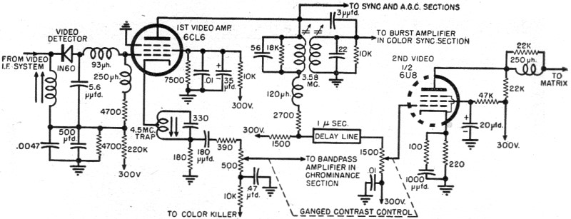
Fig. 6 - Video amplifier circuit using two pentodes
and a 3.58 mc. trap in the first video plate circuit for recovering the 3.58 mc.
burst signal for color synchronizing.
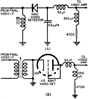
Fig. 7 - Two types of video second detectors found in color
TV sets. (A) Germanium diode; (B) triode vacuum tube with grid and plate connected
to form a diode.
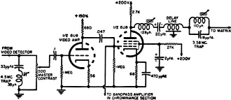
Fig. 8 - Video amplifier circuit using a triode-pentode
tube.
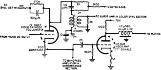
Fig. 9 - Cathode follower video amplifier circuit for color
TV.
Luminance Channel
The video signal is demodulated in the video detector (Fig. 7), providing
an output 0 to 4 mc. monochrome signal plus the I and Q color sidebands. (The color
subcarrier, it will be remembered, was deleted at the transmitter.) The detector
itself may be either a germanium diode (1N60 or its equivalent) or one section of
a vacuum tube. There appears to be a definite swing toward the germanium crystal
but vacuum tubes are still widely used.
Beyond the detector, both the monochrome and color sideband signals are applied
to at least one stage of amplification before they are separated. In the circuit
of Fig. 8, the output from the video second detector is applied first to the
triode section of a 6U8, then to the pentode section. Both signals remain together
only in the triode because at the grid of the pentode, a portion of the signal is
fed to the bandpass amplifier, which is the input stage to the chrominance section
of the receiver. Hence, separation of the monochrome and color signals might be
said to occur at the output of the triode video amplifier.
The second video amplifier in Fig. 8 deals solely with the monochrome portion
of the total color signal. This fact is further accentuated by the 3.58 mc. series
trap which is present in the plate circuit of this stage. The trap attenuates any
3.58 mc. color subcarrier voltage which may be present here in order to prevent
it from reaching the picture-tube screen and producing a visible interference pattern.
The presence of the 3.58 mc. trap limits the response of the luminance or monochrome
channel to a somewhat lower value, usually 3.0 or 3.2 mc. Since most present monochrome
receivers operate within this bandwidth, both in their i.f. and video amplifier
systems, any loss of detail will be no more apparent on color sets than on black-and-white
sets.
At this point the reader may wonder why a special 3.58 mc. trap is required when,
in fact, no 3.58 mc. color subcarrier is being sent with the signal The answer rests
in the fact that while it is true that at no time is there any voltage at precisely
the 3.58 mc. frequency, the phase excursions of the color signal cause the carrier
to move back and forth from frequencies above 3.58 mc. to frequencies below 3.58
mc.
Furthermore, most of the color energy is concentrated in the sidebands around
the 3.58 mc. frequency and if we remove the bulk of this energy with a trap, we
minimize any tendency of the color signal to produce interference patterns on the
screen.
Another fact to note is this: The frequency of the color subcarrier (and hence,
the frequency of its sidebands as well) was purposely chosen so that all this energy
would fall midway between the clusters of energy of the monochrome signal. Any color
signal reaching the screen of a monochrome receiver will tend to at least partially
cancel itself out on successive frames so that its visibility is reduced. The same
action occurs in a color set when the color signal reaches the screen via the luminance
channel. Hence, the combination of the 3.58 mc. trap with the frequency interlace
principle act to reduce the visibility of any interference pattern from this source
to a considerable degree.
EDITOR'S NOTE: Part 1 of this series, which appeared in the
March, 1954 issue, explained color mixing and its application in color TV. Part
2, appearing in the April issue, described the NTSC color signal. The block diagram
of a typical color TV receiver was described in the May issue. This and forthcoming
articles will describe and analyze the various circuits used in present color TV
sets.
In view of the many requests received, RADIO & TELEVISION NEWS will publish
this series in reprint form. The first three parts are in a single unit (50 cents),
the balance will be reprinted in individual parts at 20 cents each. For quantities
of 50 or more, write for quotations. Address your inquiries to RADIO & TELEVISION
NEWS Reprint Editor, 866 Madison Ave., N.Y. 17, N.Y.
Returning to the circuit of Fig. 8, the luminance signal is finally applied
to the matrix section where it combines with suitable I and Q signals to provide
the original red, green, and blue voltages.
Two additional representative video amplifier systems are shown in Figs. 6 and
9. The circuit in Fig. 6 is taken from an RCA schematic and employs a 1N60
crystal diode as the video second detector. The output of this stage is fed to a
6CL6 video amplifier. Here both chroma and monochrome signals are amplified. The
monochrome signal is then transferred to a second video amplifier and from this
stage to the matrix network. The chroma signal is taken from the cathode circuit
of the 1st video amplifier and transferred to the bandpass amplifier which stands
at the head of the chrominance section.
There are a number of things to note about Fig. 6. A 3.58 mc. resonant circuit
in the plate circuit of the 1st video amplifier transfers the 3.58 mc. signal to
a burst amplifier for use in the color sync section of the receiver. The same arrangement
also attenuates the amount of 3.58 mc. voltage reaching the second video amplifier.
The response of this latter amplifier extends to approximately 3.2 mc., enabling
it to impose additional attenuation on the color subcarrier.
Connection to the sync and .g.c. circuits is made at the plate of the 1st video
amplifier. Also, a 1.0 microsecond delay line is inserted in the path of the luminance
signal between the 1st and 2nd video amplifiers. The delay line is terminated in
a 1500-ohm potentiometer which serves as a contrast control for the luminance signal.
A contrast control for the chrominance portion of the signal is mechanically ganged
to the luminance contrast control, thereby insuring that both signals will be varied
in equal amounts. This is required to maintain the proper voltage relationship between
the two signals.
A 4.5 mc. trap in the cathode leg of the 1st video amplifier attenuates any 4.5
mc. voltage that may develop , in the video detector through the beating of the
video and sound carriers.
For the color TV video amplifier circuit shown in Fig. 9, the detector stage
is formed by using one-half of a 6BK7 duo-triode. The grid and plate are tied together
so the triode function as a diode. The second triode section of the 6BK7 is operated
as a cathode follower, thereby permitting a number of circuits to obtain their signals
from the detector without imposing any capacitive loading on this stage.
The plate circuit of the cathode follower provides signal voltages for the sync
separator, a.g.c., and burst amplifiers. The cathode of the same tube contains a
500-ohm potentiometer which provides the signal for both a luminance amplifier and
a bandpass amplifier and controls the contrast for both channels simultaneously.
The brightness or luminance signal is amplified by a single triode stage and
then passed through a 1.0 microsecond delay line that is terminated in the matrix
network. There are no special traps in this circuit, but response falls off rapidly
beyond 3.2 mc. attenuating any color subcarrier and 4.5-mc. voltages that might
be present.
Color and Monochrome (B&W) Television
Articles
Posted October 20, 2021
(updated from original post on 9/1/2013)
|