|
February 1939 Radio News
 [Table of Contents] [Table of Contents]
Wax nostalgic about and learn from the history of early
electronics. See articles from
Radio & Television News, published 1919-1959. All copyrights hereby
acknowledged.
|
"Modern" used in the title
of anything has always bothered me since it is utterly ambiguous unless you
know the era of the authorship. There are plenty of books using "Modern Medicine"
in the title that describe bloodletting as a treatment for various diseases
or swallowing mercury to cure constipation (and just about everything else*).
Accordingly, apologies to anyone searching for 2021-modern television information
who might have wandered in here hoping to find useful information. However,
if you are looking for historical data regarding the evolution of broadcast
television, then you might be in the right place.
As usual when reading this kind of article from a 1939 issue of Radio
News magazine, I am amazed to see accounts of the very first thoughts on
the path technology takes toward where we find ourselves in 2021. There are
basically two types of "visionaries" - those who first come up with a new idea
and those who actually implement the vision. Often the same person qualifies
for both categories. Being the first person to think up the idea of sending
voice signals or images through the air to a remote location is not such a big
deal, but being the first person to design and build a working system is a very
big deal. If you look through the large list of television history articles
at the bottom of the page, you will find ones where some of the earliest concepts
of TV were demonstrated. An electromechanical system might seem ridiculous today,
but when there was no other working model out there, it was considered miraculous.
In short order the manufacturers realized that such configurations would be
impractical in the long run, and in a short period of time fully electronic
systems were conceived. Both electrical and mechanical television required precise
timing. As author M.W. Thompson put it: "For this new miracle of the air waves
is a matter of timing far finer than ever was achieved by Rockne's immortal
Four Horsemen, the bat of the Yankee's Babe or a Bobby Jones iron shot. The
successful maneuvers worked out for the triumph of the electrons, by coaches
Zworykin, Maloff, Farnsworth, DuMont, Preisman, etc., are timed in microseconds,
and consist of "blanking," "pulses," "interlace," "keystoning" and many others."
* From the Cracked.com website #9: "If you lived more than 100 years
ago, you simply weren't considered healthy if you weren't leaking silver from
at least one orifice." (I shan't link to it)
Introduction to Modern Television

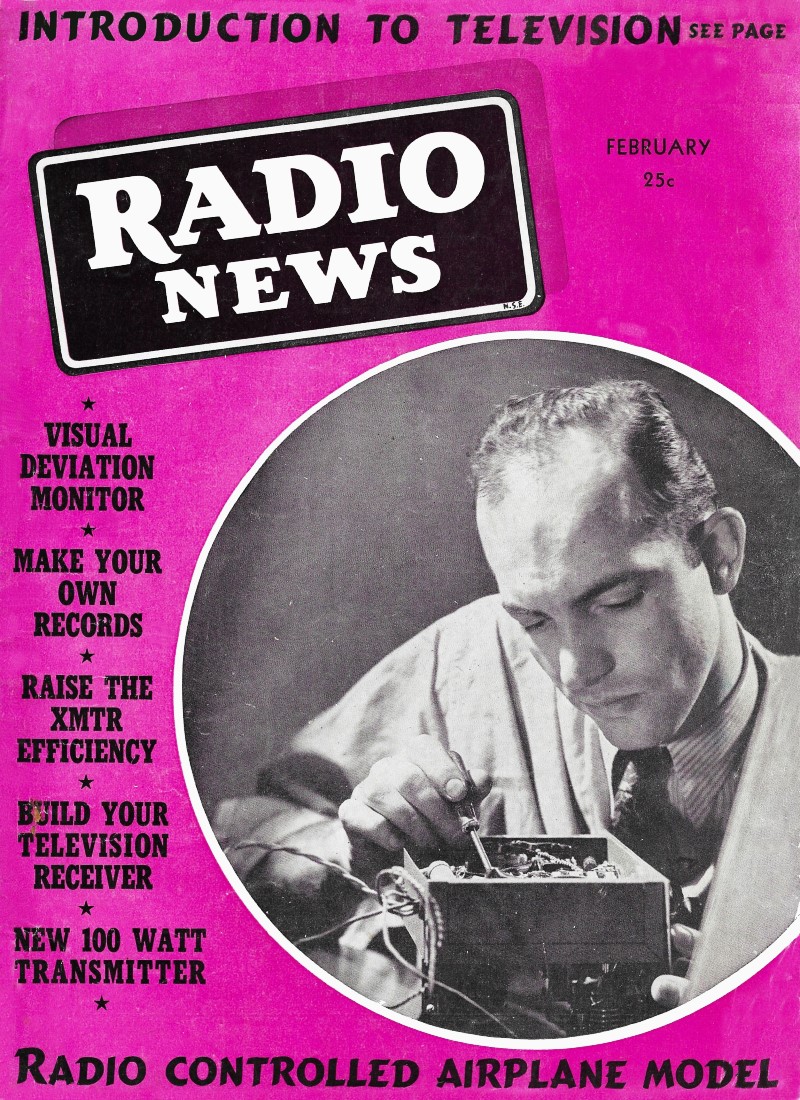
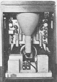
The television eye, or camera includes an iconoscope and
associated amplifiers on a movable stand .
By M. W. Thompson
Television Engineer, Chicago, Illinois
Here is your introductory course to television written so that all the difficulties
are made understandable and very easy.
You gentlemen with more than the average broadcast listener's interest in
radio, who intend getting acquainted with Miss Television during her "coming
out" parties of the next few months, will find this fascinating newcomer speaks
a new and strange language. Her sense of time is not that of seconds, minutes
and hours, but is in terms of "H" and "V" - 3H, 0.15H, 0.10V and 0.07V - in
which "H" is 1/13230th-second and "V" is 220 1/2 H's.
For this new miracle of the air waves is a matter of timing far finer than
ever was achieved by Rockne's immortal Four Horsemen, the bat of the Yankee's
Babe or a Bobby Jones iron shot. The successful maneuvers worked out for the
triumph of the electrons, by coaches Zworykin, Maloff, Farnsworth, DuMont, Preisman,
etc., are timed in microseconds, and consist of "blanking," "pulses," "interlace,"
"keystoning" and many others.
The long-debated matter of "when should television be released" was brought
to a head and settled last June when the RMA Television Committee voted approval
of a set of Television Transmission Standards for this country. As the RMA and
the FCC have been in constant touch on this subject, it seems a certainty that
the recommendations will be accepted by government authorities.
One thing should be made clear at this point. The system of television to
which this series will give the greater space is most certainly not the only
way in which this modern miracle can be accomplished; it is, however, the result
of many months of work by the Television Committee of R.M.A. and represents
the standards for transmission and reception that will, apparently, be general
practice in this country.
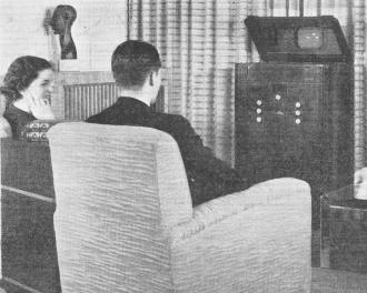
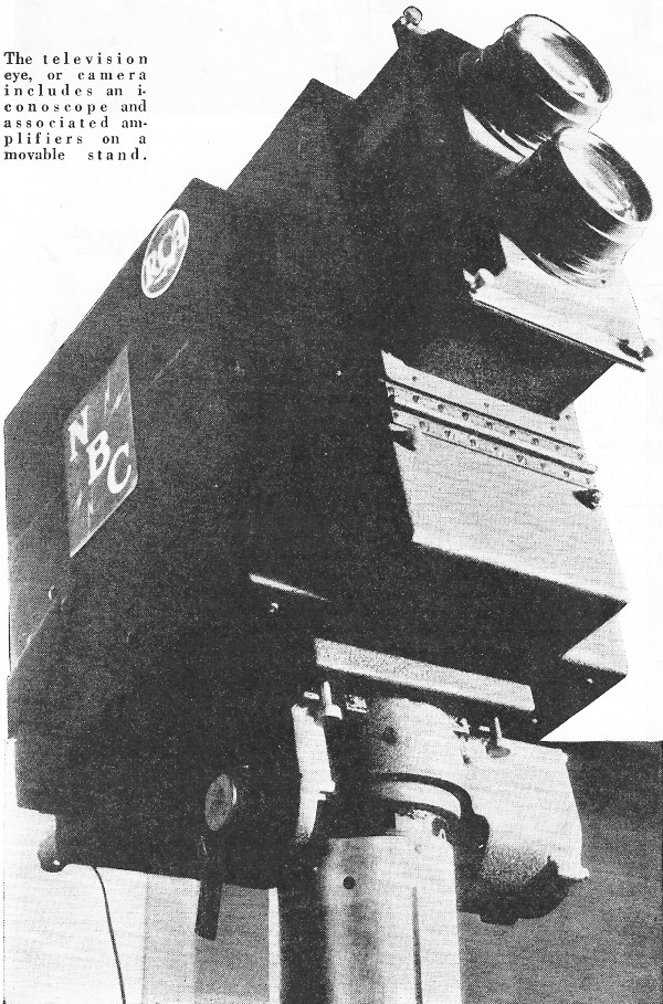
The newest television receiver will be so made that more
than one person will be able to enjoy the broadcasts.
There is much of merit in the developments of Marconi, Telefunken, Fernseh,
Mihaly-Traub, Scophony, Dumont, Farnsworth and many others. While it appears
that American practice will be developed around electron optical scanning systems,
based on the cathode ray tube, equally good results have been achieved with
mechanical optical systems. Research into the work done both here and abroad
during the past ten years, brings to light an almost unbelievable number of
combinations of lenses, apertures, prisms and mirrors mounted on drums, spirals
and discs. As this is being written, announcement has been made by Scophony,
Ltd. (British) that a $10,000,000 American affiliate will be formed to market
receivers utilizing mechanical optical designs. Allen Dumont has an excellent
system of television which involves no synchronizing signals, has 4-to-1 instead
of 2-to-1 interlace, and utilizes two carriers. Over in England they use "negative"
modulation which means that highest amplitude is white rather than the synchronizing
pulse level in blackest black, and the sync pulse level is zero radiated power
where our standards of "positive" modulation result in white. Should one care
to make a careful study of the work of many very brilliant minds and form his
own opinion of the relative merit of each one's methods, it will be interesting,
and definitely instructive; the fact will remain, however, that the electron
optical systems are going to dominate commercial television just as gasoline
motors outnumber diesels, there will be synchronizing signals transmitted, 441
will be the generally-used line frequency, and sync signals will be above blackest
black.
In this first article, I will present briefly the many features, new to radio
men, that are essential to commercially practical television, then in the second
article explain with circuits and charts how they are accomplished, in both
transmission and reception, then, with later articles, bring everyone up to
the point where he can intelligently plan and construct his receiver. While
few of us will attempt the construction of a television transmitter, it is essential
to the building, altering or servicing of a receiver, that one know all the
whys and wherefores of the complete system, as it is about to be handed to a
more-than-expectant public.
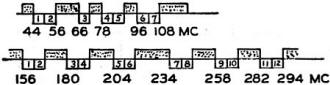
Figure 1 - Television channel frequency allocations.
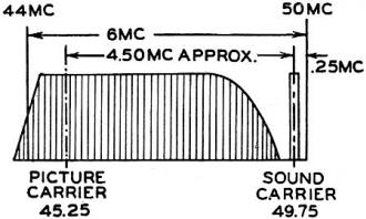
Figure 2 - Video carrier diagram.
First of all, television broadcasting is to be done in the ultra high frequency
spectrum, and, to start, seven channels have been assigned for this service
between 44 and 108 megacycles, and another twelve between 156 and 294 megacycles
(see Figure 1). This is necessary as it was only in this division of the useful
frequencies that enough frequencies were available to permit a few channels
with the relatively wide sidebands required (a television channel is six megacycles
in width). Here also, reflections from the "Heaviside" layer occur but seldom.
Reflections would be disastrous, as the difference in time between the arrival
of the ground wave and that of the reflected wave would produce images in offset
pairs or "ghosts."
Each channel is complete in itself, that is it will include both the video
(picture) and the audio (sound) transmission, and these will, in every channel,
be a definite distance apart. Thus they can be tuned-in simultaneously, heterodyned
by one oscillator, and each diverted into its own intermediate amplifiers. How
this works out is illustrated in Figure 2. For this example, the channel in
use at the Empire State Building (N.B.C.) transmitter is chosen - the channel
from 44 to 50 megacycles (mc.).
It has been found that the wider the video sidebands, the better the detail
and entertainment value, so, rather than transmit both sidebands (video) and
have each be 2.5 mc. deep, it will be the practice to utilize but one sideband
and have it, roughly, 4.0 mc. deep. The other will be suppressed. In Figure
2, the video carrier is shown as 45.25 mc. and placed 1.25 mc. from the 44 mc.
(lower frequency) edge of the channel. Its sideband is about 4.0 mc. deep. The
sound carrier is at 49.75 mc., placing it 4.5 megacycles above the video carrier
and 0.25 mc. from the 50 mc. (higher frequency) edge of the band. This 4.5 mc.
separation, and the 0.25 mc. placing of the sound carrier, are in the recommended
standards.
If, at the receiver, we tune an oscillator to 58 mc., and have it heterodyne
the 45.25 and 49.75 mc. carriers, we automatically secure the RMA standard sound
intermediate frequency of 8.25 mc. and the video intermediate frequency of 12.74
mc. Whether one tunes to the 44-50, the 50-56 or the 78-84 mc. channel, the
two carriers will tune correctly and heterodyne to their proper i.f. passbands.
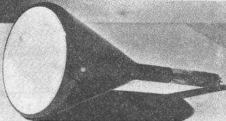
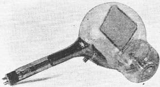
The Kinescope which makes the reception of television signals
possible.
Probably the easiest way to visualize the "pickup" and recreation of television
transmission of a scene is to imagine that you have before you, as a photoprint,
the scene to be transmitted, as it would be at any given 1/30th-second. You
have a current-generating pencil, from which a wire leads to the transmitter
- you draw a straight line across the top edge of the picture, and, as you go
over a black spot the current generated increases, while a gray spot produces
less current, and a white area would result in no current flowing. Obviously,
using a photograph, the current would constantly be changing.
Now you draw another line as close to the first as possible, so that a total
of 441 lines will cover the picture completely. When you have finished, every
point of the picture will have been represented by a current, either strong
or medium or weak, flowing from your pencil. In television, a tiny stream (or
beam) of electrons is caused to travel, just as you did it, over the image picked
up by a lens and a complex variety of cathode-ray tube called an Iconoscope.
This is called "scanning" and it results in a constantly-varying current, modulated
onto a high frequency carrier, which, when received, can be re-created into
an identical picture by another beam on the end of another type of cathode-ray
tube termed a Kinescope.
While cathode-ray tubes, as used in television, will be analyzed and explained
in detail in the next article, I present in Figure 3 a simplified sketch of
the Iconoscope and Kinescope, to make the current discussion more readily understandable.
The pickup of a scene is, in principle, not difficult to understand when an
illustration is available. The left wall of the Iconoscope, as shown in Figure
3, is of exceptionally clear, highly-polished glass, with a lens of the order
of f2.8 or f3.5 mounted at correct focal distance so the scene to be transmitted
is reduced to proper size on the Signal Plate within the tube. As the electron
beam systematically covers the image on the Signal Plate, a constantly-varying
current is caused to flow to amplifiers and the transmitter.
The modern television receiver is a bit more complicated
than the BC set.
At the receiving end, this varying current, which is stronger as the picture
- is darker and weaker as the picture tends toward white, varies the intensity
of the electron stream in the Kinescope as the beam scans the inner surface
of the glass end of the tube. As this inner wall of the tube is coated with
a preparation (may be either a sulfide or a silicate of zinc) which is highly
luminescent, the original scene is recreated in approximately 225,000 . pin
points of light with surprising fidelity. The negatively-charged particles that
compose the beam are moving with velocities of the order of 30,000 miles per
second.
Thus, what one will really see is a rapid sequence of pictures as "scanned"
by a lightning-fast electron pencil. To avoid flicker, it was known that 24
complete pictures (movie standards) or better, would have to be created per
second on the end of the Kinescope. The number 30 was chosen, because, being
a multiple of the 60-cycle supply frequency, hum difficulties could more readily
be avoided. Hum would, in this case, show itself as a dim pattern moving across
the picture.
Further to eliminate flicker, it was decided to "scan" the image in a manner
known as "interlacing" (see Figure 4). This means that, instead of picking up
our lines in regular 1, 2, 3, 4, 5 order, we pick them up as 1, 3, 5, etc.,
until we have 220 1/2 lines and then jump back and get 2, 4, 6, etc., through
another 220 1/2 lines - each complete operation taking not more than 1/60th-second.
The full set of 441 lines is known as a "frame" while each half is a "field."
Quite a few factors entered into the choice of 441 as the correct number
of scanning lines; any less than this did not give satisfactory detail from
a complex scene, while more than this created serious problems. Important, however,
as will be shown later, the number has simple factors and can be had by multiplying
odd numbers - 3x3x7x7. This enters into the generation of synchronizing signals
at the transmitter.
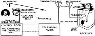
Diagram showing the various stages of the television and
audio broadcast.
The heart of the television transmitter.
Which brings me to the all-important matter of synchronization. Most of the
devices, and many of the practices, essential to successful transmission of
images were developed many months, and even years, ago. Video transmission is
very similar to sound transmission insofar as modulation, envelope, detection
and amplification are concerned - the Iconoscope and Kinescope tubes have been
in laboratories quite awhile - but until RMA pooled the ideas and plans of the
various experts, and set standards, everyone had his own favorite ideas for
synchronizing - and receivers could not be built with any assurance that their
synchronizing systems would match those of a nearby transmitter.
At first thought, it would seem that the speed of the scanning beam in a
receiver's Kinescope could readily be set to the speed of the scanning beam
in the transmitter's Iconoscope, and one could sit back and forget them. Unfortunately,
this does not work out in actual practice. So accurately must these two electron
beams function together that it is necessary to inject a synchronizing "pulse"
into the signal not only at the end of every 1/60th-second field, but also at
the end of every 1/13230th-second scanning line, and then make provision for
the separation of these pulses from the video signals in the receiver.
To use the language of the RMA Recommended Television Standards Report, I
will, hereafter, refer to the length of time required from the start of one
line to the start of the next line in a field as "H," and the time required
from the start of one field to the start of the next as "V." These times are,
of course, 1/13230th-second and 1/60th-second respectively.
To see how they are used, I now refer to Figure 5. The upper half illustrates
the television signal covering the bottom edge of the picture in one scanning
field ("A") and the top edge of the following field ("B"); the lower half of
Figure 5. portrays the signal during transmission of the bottom edge of the
second field ("B") and the top three lines of what would be a third field C'C").
This is necessary to show the differences in pulse arrangement, which explain
how interlacing is accomplished.
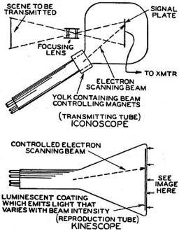
Figure 3 - Simplified sketch of the Iconoscope and Kinescope.
As in voice transmission, the carrier provided for video transmission has
a definite amplitude (voltage maximum) which it maintains evenly until modulated,
whereupon the voltage rise in each sideband varies with the impressed signals.
In the television transmitters and receivers, it is so arranged that full black
(of the picture) will be at 75 to 80% of maximum amplitude. The remaining 25
or 20% is to be used for synchronizing pulses. Thus, all variations in the image
transmitted are taken care of by variations-in carrier voltage from zero to
75 or 80% of maximum amplitude.
Since we have full black at 75% amplitude, anything that may be done with
the other 25% would not be visible on our Kinescope, and it is here that we
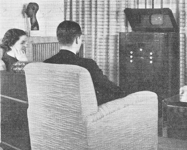
put the synchronizing pulses. At the left end of the upper half of Figure 5
we come into the middle of the fifth line from the bottom of the picture of
one field. As illustrated, it is going from dark to light (sloping down). The
narrow upright pedestal shown represents the last 15% of this line, at the right
edge of our transmitted picture. What is called a "blanking pulse" is injected
which immediately jumps the carrier to full black. In other words, we do not
"see" the last 0.15H on each swing of the Kinescope beam.
The narrower extension on the top of the pedestal is the "horizontal synchronizing
pulse," whose job it is to swing the traveling Kinescope beam back to the left
for the start of the next line (4th from bottom) while a condition of full black
exists. This horizontal synchronizing pulse starts 0.01H after the front edge
of the blanking (full black) pedestal pulse. It lasts but 0.08H in time, then
the voltage drops back to the blanking pulse level for 0.06H more, and, at its
end, we are starting the 4th from the bottom line of the picture. This cycle
continues through the last line of picture.
You will note a vertical broken line identified as "Bottom of Picture-Field
A." This is the bottom edge of that which is visible; our electron beam will
continue swinging but the final 15 to 22 lines of the field will be blanked
out or black. The recommended standards say this period, known as "vertical
blanking" shall be 0.07 to 0.10 of the time of one field (1/60th-second) which
is, roughly, 15 to 22 lines of our 220 1/2 per field.

Figure 4 - Television raster scan.
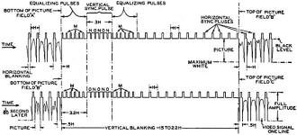
Fig. 5 - A diagrammatic breakdown of a television signal.
With the Kinescope held black, six narrow pulses, termed "equalizing pulses"
are introduced. They are 0.04H wide and spaced at 0.5H intervals, beginning
0.01H after vertical blanking began. Three of these are, in effect, horizontal
synchronizing impulses to keep the beam horizontally synchronized; the three
marked "M" are necessary to assure proper interlace in the receiver, and their
action will be described in article three.
The vertical synchronizing pulse, which comes next, requires the time 3H.
It is composed, as shown, of six 0.46H pulses and six serrations or slots which
are 0.04H each. It should be noted that the front edge of the vertical synchronizing
pulse and two of these serrations (0) correspond in their timing with the horizontal
synchronizing pulses. The other three (N) are necessary to make identical the
vertical synchronizing pulses of odd and even fields (see the vertical synchronizing
pulse directly below in the following field).
While these slots are shown with vertical sides, because they are so small
in the illustration, the sides are really sloping, so there is a slanting fall
on one side of each slot equal to 0.005H in time, and a slanting rise on the
other side of 0.005H in time. That is only 5/1000th of 1/13230th of a second,
but these slopes are necessary that a wave of the proper form be supplied to
the deflecting circuits of the receiver's Kinescope.
While the vertical synchronizing pulse has now thrown the Kinescope beam
back to the top of the picture for the start of another field, there remain
six more equalizing pulses, which must be present for the same reason as was
the first group. A series of horizontal pulses then follows before the vertical
blanking is removed, and the picture is resumed. The number of such pulses at
this point may vary from approximately six to thirteen and this will not affect
reception, except that it shortens, the height of the picture by an infinitesimal
amount if more are used. At the point marked "Top of Picture-Field B" the vertical
blanking ends and slightly over four lines of the next field are shown.
The lower half of Figure 5 is similar in its cycle of pulses to that of the
previous field, but certain features should be stressed. Note that the last
line of Field B (odd field) is not complete when the vertical blanking begins
at the bottom of Field B's picture. These are (presuming 30 lines of blanking
per frame) lines 407, 409 and 411, and their timing must be 1/2H "off" in relation
to those above in Field A (even field) which are 406, 408 and 410. At the right
end of the lower illustration, a half video line is indicated following the
finish of vertical blanking, whereas above it, a full video line is shown. In
the upper drawing, these top-of-field (B) video lines are 1, 3, 5, 7, etc.,
while below, these first lines are 2, 4, 6, 8, etc., of an even field (C).
When the fact that "an aspect ratio of 4:3 is recommended to conform with
existing motion picture practice" is added, we have concluded our review of
the more important introductory features of television. This quoted sentence
simply means that the height of the picture shall be 3/4 the width, regardless
of size of Kinescope used.
For Additional Reading
Electron Optics in Television I. G. Maloff and D. W. Epstein McGraw-Hill
Book Company
Electronic Television George H. Eckhardt The Goodheart-Willcox Co.,
Inc.
Television with Cathode Rays Arthur H. Halloran Pacific Radio Publ.
Co.
Color and Monochrome (B&W) Television
Articles
Posted March 22, 2021
|