|
When minimum signal loss in a transmission
line is required for maximum power transmission between the receiver and/or transmitter,
nothing come close to waveguide. Waveguide is very expensive and for frequencies
below a gigahertz or so, very impractical (or even impossible) due to the required
physical size. It has the advantage, too, of being nearly impervious to outside
interference or leakage to the outside, and it can handle extremely high power levels.
Waveguide can be installed in almost any manner and anywhere without concern for
signal disruption. Its biggest vulnerability is probably arcing due to contaminants
within when the system has not been purged of humid air and backfilled with a gas
such as dry nitrogen. Coaxial cable has many advantages of waveguide, but is less
expensive and easier to install and maintain. It biggest negative is relatively
high signal attenuation unless very large gauge inner conductor sizes are used -
which adds to expense and handling difficulties. In-between is
twin
lead transmission line (including ladder line). At frequencies up through about
a gigahertz, properly installed twin lead line has after a quarter or less of the
loss of "normal" size coaxial cable, but more than waveguide would have if available.
In the days of rooftop television antennas, twin lead was very inexpensive, even
for the high-end foam-filled stuff. Twin lead's biggest drawback by far is its sensitivity
to routing near obstacles (buildings, dirt, towers, etc.). If you are old enough
to remember twin lead cable running from the roof of your house to the TV, then
you know of what I write.
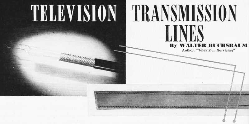
Television Transmission Lines
By Walter Buchsbaum
Author, "Television Servicing"
A. discussion of the principal considerations involved in selecting and installilng
TV lines.

Fig. 1 - Federal Telephone's recently developed 300-ohm shielded
television cable. Fig. 2 - A 300-ohm twin-lead with leads separated by polyethylene.

Fig. 3 - Reflections appearing as ghosts or multiple images caused
by line mismatch.
Because of the complexity of the TV receiver itself and the variety of available
antennas, these two items are usually the main considerations in installing a TV
receiver. The proverb about the weakest link in the chain applies to television,
especially in the case of the transmission line from the antenna to the receiver
which is often the weakest link and therefore, a source of trouble. As the name
indicates, the transmission line transmits the signal from the antenna to the receiver,
but it is more than just a set of wires carrying electricity. It is our purpose
to show the electrical characteristics, function, and requirements of television
transmission lines together with their limitations and corrective measures.
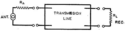
Fig. 4 shows the electrical circuit of the antenna and the TV receiver input
as well as the transmission line between the two. The antenna can be considered
as an a.c. generator with an internal impedance RA which works into a
load RL. The transmission line then has the function of delivering the
output of the antenna to the load with a minimum of losses and distortion. To get
maximum power transfer the internal impedance of the transmission line must equal
that of the generator and, at the receiver end, that of the load. In other words,
we must have correct impedance match both at the antenna and at the receiver to
get maximum efficiency from this system. It is easy to see that in a weak signal
area this efficiency can make the difference between a usable or unusable signal.
Another effect of improper impedance match is reflections on the line which will
be explained in detail later. These reflections appear as ghosts or multiple images
on the screen and may be strong enough to completely ruin the picture as in Fig.
3. Excessive attenuation also results in weak pictures and must be avoided, especially
in fringe areas.
The most frequently used type of television transmission line is the 300 ohm
twin-lead shown in Fig. 2. It consists of two conductors of stranded copper wire
set into a flat ribbon of polyethylene. Although polyethylene is a very good insulator
some capacity exists between the two wires. When current flows through a wire a
magnetic field is set up around it so even a perfectly straight wire must be considered
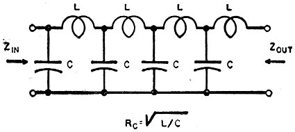
as having some inductance. The complete transmission line then can be considered
as having both inductance and capacity and its equivalent electrical circuit is
therefore shown in Fig. 5. The first L and C at the left of the diagram represent
the inductance and capacity per unit length; this could be per foot, yard, meter,
or mile, and as long as we know the values and the unit we can calculate other useful
characteristics. One of the most important is the characteristic impedance of the
transmission line. This RC is the impedance in which a particular transmission
line must be terminated so as to deliver maximum
power and have no reflections. In the case of the twin-lead shown in Fig. 2,
300 ohms is the characteristic impedance and when this line is terminated by a 300
ohm resistor it will deliver maximum power and have no reflections. and therefore
no standing waves on the line. One formula for RC is given in Fig. 5,
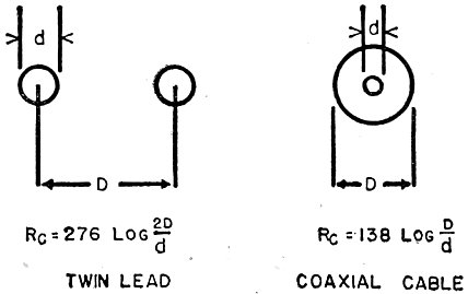
another makes use of the physical dimensions of the line as shown in Fig. 6.
Where physical dimensions are concerned, a considerable difference exists between
twin-lead and coaxial cable and a further variation depends on the type of insulating
material used. Polyethylene, the material used for most TV lines, has a dielectric
constant which is more than twice as high as air. Open wire lines must, therefore,
have wider spacing between wires than those molded in polyethylene.
Standing Waves

Fig. 4 - RF transmission line in system.
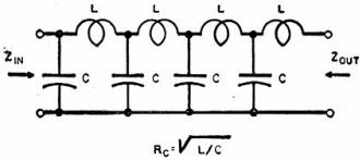
Fig. 5 - Twin lead distributed element circuit model.

Fig. 6 - Physical dimensions of twin line and coavxial cable.
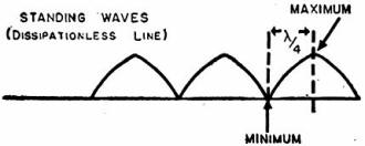
Fig. 7 - Standing waves on transmission lines.
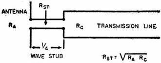
Fig. 8 - Transmission line tuning stub.
When a transmission line is terminated in anything but its characteristic impedance,
some of the signal sent through it will be reflected back from the improperly terminated
end. That this comes about can be proven mathematically and the truth of this statement
verified experimentally. These reflected signals are usually out-of-phase with the
original and therefore reduce the original signal strength at the receiving end.
Another explanation for the loss in signal at the load is that when some of the
transmitted energy is used up in reflections, less is available at the load. The
reflected signal, together with the original signal, keeps up a constant field around
the transmission line, because each successive cycle produces the same reflection,
and again the same instantaneous field. The total effect is that of a constant r.f.
field of a pattern like that shown in Fig. 7. The distance between successive points
of maximum or minimum is half the wavelength of the transmitted signal if the line
is of the open-air type. If polyethylene is used, the distance between these peaks
and valleys will be slightly less than half the wavelength. The Greek letter lambda
(λ) in Fig. 7 is the conventional symbol for wavelength. In laboratory procedure
it is possible to get a better picture of this standing wave field by using a fairly
strong r.f. signal and placing a small antenna probe and diode rectifier near the
line. The rectified r.f. is then measured and by setting up a ratio between the
voltage obtained at a maximum and at a minimum point, the standing wave ratio is
obtained.
Standing-wave ratio = Emax/Emin
Thus if the s.w.r. is close to 1, this indicates that the line is terminated
properly and no reflections take place. In television work it is desirable to get
an s.w.r. as close to 1 as possible and practical values will range from about 1.05
to 1.2.
Dissipation
Up to now we have assumed that the transmission line is composed entirely of
inductive and capacitive elements and therefore would not have any dissipation.
Although most types of TV lines have a fairly small d.c. resistance due to the copper
conductors, some dissipation is encountered in every transmission line. By that
we mean the loss in power due to heating up the copper conductors and the losses
due to the dielectric between conductors. In the average TV installation these losses
are negligible, but where lengths of 1/2 to 1 mile are concerned the dissipation
losses present a serious problem. One way to overcome them is by means of open-wire
lines. To reduce the d.c. copper loss the conductors are of larger size and to minimize
dielectric losses the two wires are kept several inches apart by means of low-loss
polystyrene spacers. Such a transmission line must be well removed from all grounded
objects and suspended with suitable insulators.
The standing-wave pattern, shown in Fig. 7, holds true only for a line having
no dissipation and such a line, is not practically feasible. Therefore, the effects
of dissipation on the standing-wave pattern must be considered, even though, just
like the actual losses, this effect will be slight for TV transmission lines. Since
the losses in the line reduce the signal strength as it travels down the length
of the line, the reflected signal will also be reduced. For a line having considerable
dissipation the standing-wave pattern will not be constant as shown in Fig. 7, but
the height of each maximum point will be slightly less than the one before as the
pattern progresses towards the sending end. On very long lines this means that while
the s.w.r. may be quite high at the improperly terminated receiving end, it may
be negligible at the transmitting station. When specifying s.w.r. for longer lines
the distance from either end of the line should be given.
Tuned Line Effects
If a transmission line has exactly the same length as some multiple of the wavelength
of the signal, we speak of a "tuned" line. The effects of such a tuned line length
are quite similar to the effects of resonant or tuned circuits at the resonant frequency.
The shortest multiples of the wavelengths which are practically usable are the quarter
and half wavelength sections. A shorted half wavelength of transmission line or
an open quarter wavelength act just like a series resonant circuit. Their input
impedance is zero at the resonant frequency and they represent an effective short
circuit to signals of that wavelength.
A shorted quarter wavelength or an open half wavelength, however, act just like
a parallel resonant circuit. Their impedance at the resonant frequency is very high.
These particular characteristics of transmission lines are quite useful in television
work.
Matching Stubs
One more aspect of transmission line theory merits discussion here because of
its use in TV installations, that is, the impedance matching action of a quarter
wavelength of line.
When it is desired to match different impedances, transformers are used in circuit
work. In transmission line networks, a quarter-wave matching stub serves the same
purpose. While in ordinary circuits the matching action of the transformer depends
mainly on the turns ratio, the characteristic impedance of the matching stub is
the critical factor here. As shown in Fig. 8, this characteristic impedance, Rst,
is the square root of the products of the two impedances to be matched. Assume that
a 50-ohm antenna and a 300-ohm line are to be matched. Rst equals the
square root of 15,000 which turns out to be 122.5 ohms. Since the nearest commercially
available value is 150 ohms for twin-lead, this can be used and a slight mismatch
must be tolerated. The alternative would be to make up an open wire stub according
to the formula in Fig. 6. By simple algebra we obtain the value of 2D/d, then we
need only select a convenient wire size for d and adjust the spacing D accordingly.
It should be noted that this impedance matching is not applicable to a broad
band of frequencies, just as most high gain antennas are not equally effective on
all TV channels. In most instances where separate high- and low-band antennas and
lead-ins are used, the matching stub can be designed for the center frequency in
each TV band. To use a single matching stub for both TV bands would hardly be useful
since the mismatch at the off frequencies would be just as great as without the
stub.
Application of Theory in TV
Once we understand the fundamentals of transmission line theory, half of all
problems connected with TV lines are solved automatically. Reviewing the major installation
difficulties which can be overcome by proper manipulation of the transmission line,
we find the following:
a. Weak signal due to losses on the line
b. Reflections or ghosts due to improper impedance match
c. Over-all inefficiency of line
d. Interference picked up by the antenna or line.
Foresight being better than hindsight it is wise to plan the installation in
advance and try to avoid all of these defects. The most important item in that respect
is the choice of the antenna and transmission line to match the input impedance
of the receiver. Most modern sets have a 300-ohm input or else have provision for
either 72- or 300-ohm input by means of a coupling transformer mounted near the
tuner. 52-ohm input is rare, but some older receivers may have it. To match these
impedances the most common type of line is the 300-ohm, ribbon-type, twin-lead.
Coaxial cable comes in 72- and 50-ohm types and is often preferred over twin-lead
because of its shielding effect against ignition and other noise. Recently, a special
300-ohm, shielded cable was made available by Federal Telephone & Radio Corp.
This cable is shown in Fig. 1, and has the advantage of the 300-ohm impedance, combined
with the shielding effect of the outer copper braid. When this type of line is used
connect the two inner conductors to the antenna terminals and connect the shield
to the chassis by means of a 0.1 μfd. condenser. This eliminates the danger of
shorts should the chassis be connected to the power line. In addition to selecting
the correct transmission line, the selection of the best antenna is quite important.
The choice of antenna, however, will be guided by reception conditions, number of
channels to be received, reflections, etc., rather than by impedance considerations.
As a result, the impedance of the antenna is often quite different from that of
the line. A few types such as the folded dipole, conical, and other broadband antennas
have an impedance approaching 300 ohms. Most of the high-gain, narrow-beam types
have impedances varying from 10 to 75 ohms. It is possible to get a higher impedance
when the antenna connections are made a little further from the center, but this
has the effect of loading the antenna and often cannot be done. The best procedure
is to find out the nominal impedance of the antenna to be used from the manufacturer's
data and then design a matching stub accordingly. As mentioned before, a separate
matching stub for each TV band is a necessity and the ideal, of course, would be
to have a separate antenna and matching stub for each channel.
To keep the dissipation losses to a minimum and the efficiency of the system
high, mount the transmission line well away from walls, gutters, and pipes, especially
where twin-lead is used. The mounting studs should contain either porcelain or polyethylene
to avoid further capacity to ground. Never use regular electrician's tape or paper
tape on twin-lead since they have a much lower dielectric constant and therefore
increase losses. Only poly-tape or a good grade of cellophane tape should be used.
Another "don't" concerns the practice of concealing twin-lead near a molding, tacking
it on and eventually painting over it. Invariably tacking and especially painting
will completely wreck the impedance and dissipation characteristic.
Once an installation is made and exhibits some of the defects due to incorrect
transmission line impedance or excessive losses, the remedy is naturally somewhat
harder. To make sure efficiency is really down it would be necessary to install
a new and properly matched line, unless it is possible to measure the signal strength
at the antenna and again at the receiver. A loss of more than 20% for a 50 foot
length would certainly be excessive. It is often possible to determine by inspection
whether the impedance of the antenna is matched and whether a match exists at the
receiver. To check for standing waves simply grasp the line in one hand and slide
the hand along the line over at least five or six feet and observe if the picture
changes as this is done. If the picture shifts, ghosts move, or the signal strength
changes, standing waves are present and improper impedance match exists.
Interference Elimination
The effect of "tuned" transmission line lengths can often be used to eliminate
interference before it reaches the TV receiver. As was shown earlier, a quarter-wavelength
open line or a half-wavelength shorted line represents a short circuit at the resonant
frequency. If, therefore, such a length were connected to the antenna terminals
of the TV set, the resonant frequency would be shorted out, but other signals would
not be affected too much. A good example would be the case of FM interference from
a station at about 108 mc. which could be received by beating with the local oscillator
set at 83 mc, and the receiver tuned to Channel 3. Connecting an open circuited
quarter-wavelength section of transmission line at the antenna terminals would make
this a short for the interfering signal. At the desired TV signal, however, this
would be much less than a quarter-wavelength and would represent a high impedance.
In practical applications the exact wavelength of the interfering signal need not
be known, but only an approximate idea of it is necessary. Cut the open circuited
stub longer than necessary and connect at the receiver. Then cut off 1/2 inch lengths
until the interference is eliminated.
There is nothing mysterious about the behaviour of transmission lines and once
the basic theory of this subject is understood the technician will find many applications
in designing new installations and improving the performance of existing ones. Although
not an active circuit element, the transmission line between the antenna and the
receiver is a vital link in the over-all operation of TV reception.
Color and Monochrome (B&W) Television
Articles
Posted January 17, 2019
|