Wax nostalgic about and learn from the history of early
electronics. See articles from Radio & Television News, published 1919-1959. All copyrights hereby
acknowledged.
RCA ColorTrak TV advertisement. How many of you can still recite
the familiar slogan? It is permanently emblazoned on (in?) my mind, as are so many
others from the 1960s and 70s.
You genius types might not be able to relate to the rest of us who read articles
like this one entitled "Fundamentals of Color TV: The NTSC System" and are in awe
of minds that conjure such things as the NTSC System and then build, refine, and
perfect working hardware. Making the system backward-compatible with existing black
and white (B&W) signals added to the complexity and cleverness of the solution
- akin but more sophisticated than compatibility of stereo with original mono radio
transmissions. When catchy marketing slogans like the familiar (to old folks) RCA
television advertisement claim of "Before you see the color ... Your ColorTrak
System grabs it, aligns it, defines it, sharpens it, tones it ... and locks the
color on track," what it actually means is that a very smart bunch of engineers
and scientists spent a lot of time and money designing a color tracking system
that does all those things automatically so that your picture is always optimal.
You might be tempted to think that with the LCD displays of today the color
separation, tone, brightness, hue, contrast, etc., are all automatically exactly
and consistently rendered because, after all, a precise digital signal describes
everything. Those old analog signals were more subjective than objective, after
all. However, if that was so then
there would be no need for the software color adjustment applets provided with your
monitor and notebook computer, and all those televisions sitting on the shelves
at the Large Mart would have pictures which all appear precisely the same.
Fundamentals of Color TV: The NTSC System
By Milton S. Kiver
President, Television Communications Institute
RCA's developmental 19-inch tri-color tube shown with the 15-inch version which
is in production for color sets.
Part 2. Explanation of the NTSC color TV signal, how it was developed, and why
it is compatible with black-and-white.
Perhaps the most striking feature of the compatible color television system to
the service technician is the fact that a high quality color television signal can
be fitted into the same spectrum space now occupied by a black-and-white (or monochrome)
signal. To make this feat even more astounding, we not only have the color signal,
but we have in no way disturbed the existing monochrome signal.
How is all this possible? It is all possible because of the nature of a television
signal. When we say that a television signal extends from 0 up to 4 mc., we do not
mean that it occupies every cycle of that 4 mc. In other words, the energy is not
spread continuously from one end of the band to the other; rather, it exists in
the form of bundles of energy each separated from the group above and below it by
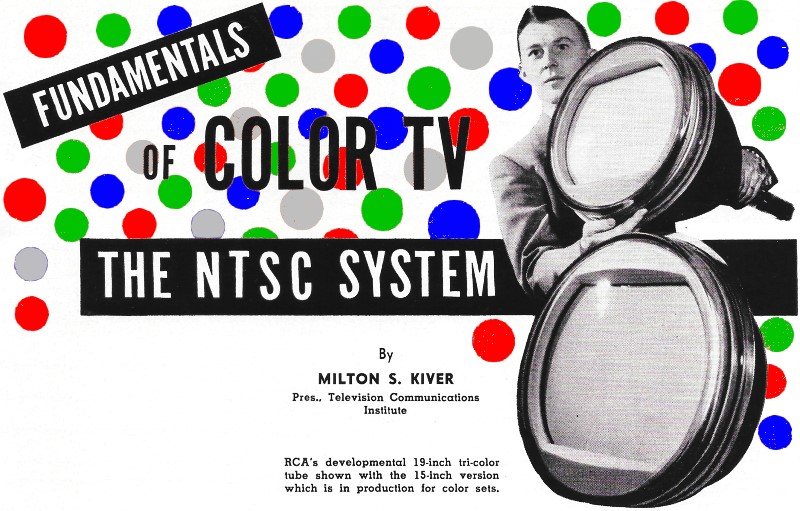
a frequency of 15,750 cycles. This is illustrated in Fig. 1, where a section of
the spectrum of a video signal is shown. Note that each bundle or cluster of energy
is distinct from its neighbors, with relatively wide, empty spaces in between. It
is into these empty spaces that the color signal is fitted. This process of fitting
one video signal in among the empty spaces of another video signal is known as interleaving.
The two signals thus can be said to occupy the same general band, although they
never come in contact with each other and hence do not, within limits, interfere
with each other.
The Monochrome Signal
The black-and-white or monochrome portion of the total color signal is equivalent
in all respects to present black-and-white signals. It is formed by combining the
red, green, and blue signals from their respective color cameras in the proportions
of: Y = 0.59G + 0.30R + 0.11B where Y is a mathematical symbol representing the
monochrome signal, G is the green signal, R is the red signal, and B is the blue
signal.
This particular combination was chosen because it closely follows the color sensitivity
of the human eye. That is, if you take an equal amount of green light, and an equal
amount of red light, and an equal amount of blue light and superimpose the rays
from these lights on a screen, you will see white. However, if you then look at
each light separately, the green would appear to be twice as bright as the red,
and six to ten times as bright as the blue. This is because the eye is more sensitive
to green than to red, and more sensitive to red than to blue. It is in recognition
of this fact that the proportions given in the formula were chosen.
Thus, the monochrome signal is composed of 59 per-cent green, 30 per-cent red,
and 11 per-cent blue, and contains frequencies from 0 to 4 mc. (The use of the letter
Y to denote the monochrome portion of the color signal is a common practice and
should become familiar to the reader.)
Other names for this monochrome signal are luminance and brightness signal. The
function of this signal is to reproduce, at the picture tube, the changes in brightness
of the picture.
The Color Signal
Fig. 1 - Representation of the signal energy distribution of
a 4 mc. video signal showing how the color information is inserted in the gaps between
the monochrome.
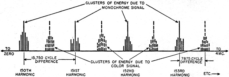
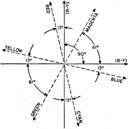
Fig. 2 - The angular position and amplitude of the resultant
carrier for various amplitudes of B-Y and R-Y. (A) The B-Y and R-Y vectors. (B)
The resultant when B-Y and R-Y are equal. (C) when B-Y is stronger than R-Y. and
(D) when the R-Y signal is stronger than B-Y signal.
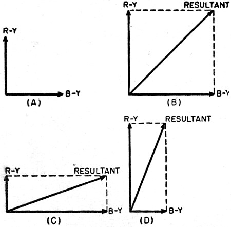
Fig. 3 - How color determines the position of a resultant vector.
(A) Equations showing compositions of B-Y and R-Y. (B) Position of resultant vector
when red field only is being scanned. See text for details.
The second component of the television signal is the color signal itself. This,
we have just seen, is interleaved with the black-and-white signal. To determine
what information this portion of the total signal must carry, let us first see how
the eye reacts to color, since it is the eye, after all, for which the color image
is formed.
A number of men have investigated the color characteristics of the human eye,
and they found that to reproduce essentially all of the colors which the eye normally
sees, we require only three so-called primary colors of light. These are red, blue,
and green. The proportion in which these colors are mixed will determine the color
produced; when all three are used, white will be produced.
The average human eye requires these three primaries only for relatively large
colored areas or objects. When the size of the area or object decreases, several
things happen. Probably the most important change that takes place is that it becomes
more difficult for the eye to distinguish between various colors. For example, blue
and green are often confused with each other, as are brown and crimson. Also, blue
tends to look like grey and yellow likewise becomes indistinguishable from grey.
Reds remain fairly distinct, but all colors tend to lose some of their vividness.
Thus, where the eye formerly required three primary colors, now it finds that it
can get by very well with only two. That is, these two will, in different combinations
with each other, provide the range of colors that the eye needs or can see.
Finally, when the detail becomes very small, all that the eye can discern are
changes in brightness; colors cannot be distinguished from grey and to all intents
and purposes, the eye is color blind.
These properties of the eye are utilized in the NTSC color system. For example,
only the larger detail is colored; the fine detail is rendered in black-and-white.
Secondly, as we shall see later, even the color information sent is regulated according
to bandwidth. That is, the larger objects receive more of the green, red, and blue
than the medium sized objects.
The color signal takes the form of a subcarrier and an associated set of sidebands.
The subcarrier frequency is approximately 3.58 mc. This represents a figure which
is the product (approximately) of 7875 cycles multiplied by 455. 7875 is one half
of 15,750, and if we use an odd multiple (i.e., 1, 3, 5, etc.) of 7875 as a carrier,
then it will fall midway between the harmonics of 15,750 cycles, If we used even
multiples of 7875, we would end up with 15,750 or one of its harmonics and this
would place the color signal at the same points (throughout the band) as those occupied
by the black-and-white signal. Refer back to Fig. 1. By taking an odd multiple of
7875, we cause the second signal to fall in between the bundles of energy produced
by the first signal, and the two do not interfere.
Now that we have a color carrier (or subcarrier, as it is known), the next step
is to provide it with enough modulation to enable the receiver to develop a color
picture. Ordinarily, the information required would consist of R, G, and B since
these are the three primary colors of light from which all of the other colors are
derived. This means modulating the color sub carrier with three different quantities.
Actually, however, we can do exactly the same job using only two quantities if we
resort to the following modification. Take the R, G, and B voltages and combine
them with a portion of the monochrome signal after the latter has been inverted
180°. This produces R-Y, G-Y, and B-Y signals. We can do this by taking a portion
of the brightness signal (Y signal) and passing it first through a low-pass filter.
This permits only the low-frequency components to get through which is satisfactory
since the color signals are also concerned only with the low frequencies. Then the
brightness signal is passed through an amplifier and inverted. If we call the brightness
signal Y, then after the inversion it becomes -Y. This is then added to each of
the three color signals or voltages to produce a G-Y, a R-Y, and a B-Y signal.
At the receiver, the original R, G, and B can be re obtained by adding Y to G-Y
to obtain G, by adding Y to R-Y to get R, and by combining Y with B-Y to get B.
Thus far, it would seem that we have only exchanged R, G, and B for R-Y, G-Y,
and B-Y. However, once this is done, it turns out that instead of requiring all
three color-difference signals, all we really need are two, say R-Y and B-Y. This
is so because G information is already present in the Y or brightness signal since
the latter contains voltages from all three colors (i.e., Y = 0.59G + 0.30R + 0.11B).
Hence, if we send along only R - Y and B - Y in the color signal to the receiver,
we can use these to obtain the G-Y information we need. For those who would like
to see proof of this, a simple analysis is given at the end of the article.
Thus, we now have only two pieces of color information to send and somehow the
3.58 mc. color subcarrier must be modulated by R-Y and B-Y voltages without conflict
to each other.
The best solution to this problem, designers found, was to take the B - Y and
R- Y signals and apply each to a separate modulator. At the same time, 3.58 mc.
carriers were also applied to each modulator, but with this difference. Their frequencies
were the same, but one carrier was 900 out-of-phase with the other. After the carriers
were amplitude modulated, they were then combined to form a resultant carrier. This
is best illustrated by means of vectors. In Fig. 2A, the B-Y vector represents the
B-Y modulated carrier; the R-Y vector represents the carrier modulated by the R-Y
voltage. When these voltages or signals are combined, a resultant is formed. If
the R-Y and B-Y signals are equally strong, the resultant will occupy the position
shown in Fig. 2B. If the B-Y signal is predominant, the resultant will be drawn
closer to it. See Fig. 2C. On the other hand, if the R-Y signal is the stronger,
the position of the resultant vector will shift toward it. See Fig. 2D. Thus, we
can see that the phase angle of the resultant will be governed by the coloring of
the picture while the amplitude (or length) of the vector will determine how saturated
the colors are.
This particular fact is of great importance in the receiver because if we somehow
change the phase of the resultant with respect to B-Y or R-Y, then the colors reproduced
on the screen will be incorrect. Hence, present circuit designs incorporate a special
phasing control which enables us to compensate for any phase shift that may occur.
The position of this control in the circuit will be covered in a later article.
Note that the B-Y and R-Y signals amplitude modulate their separate carriers
prior to the addition and so each modulated signal possesses a 3.58 mc. carrier
and a series of sidebands (like every AM signal). When the resultant is formed,
the sidebands are brought along with it.
If we were to pause now and reconstruct our total color signal, here is what
we would find. First, there would be the Y or monochrome signal and it would extend
over the entire video frequency range from 0 to 4 mc. Second, there would be a color
sub carrier, with a frequency of 3.58 mc. This carrier is modulated by the R-Y and
B-Y signals and the modulation intelligence is contained in a series of sidebands
that stretch above and below 3.58 mc. Just how far above and below is dependent
on the band of frequencies contained in the R-Y and B-Y modulating voltages. It
was discovered that the eye is perfectly satisfied with the color image that is
produced if we include color information only up to 1.5 mc., while the portion of
the image from 1.5 mc. to 4 mc. is rendered in black-and-white. Hence, the sideband
frequencies of the color modulating voltages (so far called R-Y and B-Y) need extend
only from 0 to 1.5 mc. Furthermore, we can even modify this set of conditions somewhat
because the three primary colors are required only for large objects or areas, say
those produced by video frequencies up to 0.5 mc. For medium sized objects, say
those produced by video frequencies from 0.5 to 1.5 mc., only two primary colors
need be employed. In other words, to take advantage of this situation, we need two
color signals, one of which has a bandpass only up to 0.5 mc., while the other has
a bandpass from 0 to 1.5 mc. The next problem, then, is to determine what the composition
of these two color signals is.
To appreciate the answer to this, let us return to the vector diagram showing
the R-Y and B-Y signals. This is redrawn in Fig. 3A and to this diagram we have
added the equivalent equation for Y, namely, 0.59G + 0.30R + 0.11B. For R-Y, then,
we have R - 0.59G - 0.30R - 0.11B or 0.70R - 0.59G - 0.11B and, for B-Y we obtain
B - 0.59G - 0.30R - 0.11B or 0.89B - 0.59G - 0.30R. This means that the R-Y and
B-Y vectors contain R, G, and B voltages in the proportions shown.
Now, let us suppose that the color camera is scanning a scene containing only
red. Then, no green or blue voltages would be present and the R-Y signal becomes
simply 0.70R, while the B-Y signal is reduced to - 0.30R. This set of conditions
is shown in Fig. 3B, with the position, too, of the resultant vector. In other words,
this is the position the vector would occupy when red only was being sent.
Fig. 4 - The phase of the color subcarrier depends upon the color
to be sent.
Fig. 5 - The distribution 01 the full color signal within its
allotted band.
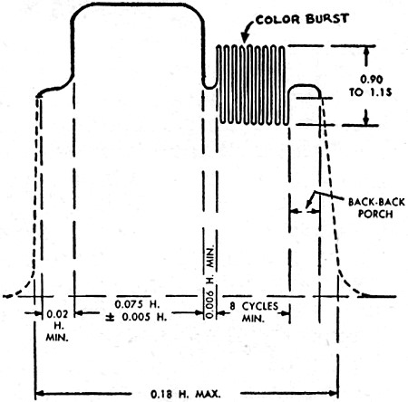
Fig. 6 - The position of the color burst for sub carrier oscillator
sync on the back porch of a horizontal sync pulse.
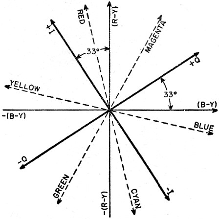
Fig. 7 - The positions of the I and Q signals with respect to
R-Y and B-Y.
By following the same process, we can obtain the position that the resultant
vector occupies when only green is being sent, or blue, or any other color formed
by uniting these three colors in any combination. A number of colors are shown in
Fig. 4 and we see, perhaps more clearly than before, how the phase of the color
sub carrier changes as the color to be transmitted varies. This, of course, brings
us back to a statement previously made, namely: the phase angle of the resultant
will be governed by the coloring of the picture while the amplitude (or length)
of the vector will determine how intense (i.e., saturated) the colors are.
The designers of the NTSC system found that while they could use R-Y and B-Y
for the color signals, better system operation would result if they chose two other
signals situated not far from the R-Y and B-Y signals. These two other signals were
labeled I and Q signals and their position with respect to R-Y and B-Y is shown
in Fig. 7.
Thus, where before we had R-Y and B-Y voltages modulating the 3.58 mc. color
sub carrier, we now substitute I and Q signals. Furthermore, the Q signal possesses
frequencies up to 0.5 mc. while the I signal is permitted to have signals up to
1.5 mc.
Now, what do we gain from this? For all color signal frequencies up to 0.5 mc.,
both I and Q are active and since they are 90° apart as were R-Y and B-Y, they
will act just the way R-Y and B-Y acted. That is, they will, in combination with
each other, produce all of the colors shown in Fig. 4. Hence, whether we use I and
Q or R-Y and B-Y as our modulating voltages for color frequencies up to 0.5 mc.,
we get precisely the same results.
Now consider the situation for color frequencies from 0.5 mc. to 1.5 mc. The
Q signal drops out and only the I signal remains to produce color on the picture
tube screen. From Fig. 7 we see that positive values of the I signal will produce
colors between yellow and red or actually a reddish orange. On the other hand, negative
values of I will produce colors between blue and cyan or, in general, in the bluish-green
range. Hence, when only the I signal is active, the colors produced on the screen
will run the gamut from reddish-orange to bluish-green.
But why do we want this? If you go back to an earlier section of this article
you will see that for medium-sized objects (say those produced by video signals
from 0.5 mc. to 1.5 mc.) the eye is sensitive only to bluish-green or reddish-orange.
Since this is so, the NTSC signal (via its I component) is fashioned to take advantage
of this fact.
We are now in a position to consider the color signal in all its aspects.
1. There is a monochrome signal with components that extend from 0 to 4 mc. This
is the Y signal.
2. The color subcarrier frequency is set at 3.58 mc. (actually it is 3.579545
mc.).
3. This color subcarrier is modulated by two color signals called the I and Q
signals.
4. The Q signal has color frequencies that extend from 0 to 500 kc. or 0.5 mc.
This means that the upper Q sideband extends from 3.58 mc. up to 3.58 + 0.5 or 4.08
mc. The lower Q sideband goes from 3.58 mc. down to 3.58 - 0.5 or 3.08 mc.
5. The I signal has color frequencies that extend from 0 to 1.5 mc. When this
modulates the color subcarrier, upper and lower sidebands are formed. The lower
sideband extends from 3.58 mc. down to 3.58 - 1.5 or 2.08 mc. If the full upper
sideband were permitted to exist, it would extend all the way up to 3.58 + 1.5 or
5.08 mc. Obviously this would prevent the use of a 6 mc. over-all band for the television
signal (video and sound). To avoid this spilling over beyond the limits of the already
established channels, the upper sideband of the I signal is limited to about 0.6
of a megacycle. This brings the upper sideband of the I signal to 4.2 mc. The video
passband then ends rather sharply at 4.5 mc. See Fig. 5.
There is one further fact that is of importance in the make-up of a color television
signal and this concerns the color subcarrier. We know that the 3.58 mc. carrier
is modulated by the two I and Q color signals. Now, in conventional modulation methods,
both the carrier and the sidebands are present when the signal is finally sent out
over the air. The intelligence (or modulation) is contained in the sidebands and
that is actually all that we are interested in. However, the carrier is sent along
because it is required in the receiver to reverse the modulation process and recreate
the original modulating voltages.
In the NTSC color system, the color subcarrier is not sent along with its sidebands
(after the latter have been formed). Instead, it is suppressed by using a balanced
modulator. This particular practice is followed for two reasons. First, by suppressing
the color subcarrier, we reduce the formation of a 920 kc. beat note between it
and the 4.5 mc. sound carrier which is also part of every television broadcast.
This 920 kc. note would appear as a series of interference lines on the face of
the picture tube. Now, it is true that the color sidebands are present and that
they can (and do) beat with the 4.5 mc. sound carrier to produce similar low frequency
beat notes. However, in any signal, the carrier usually contains far more energy
than any of its sidebands and so, when we suppress the carrier, we are, in effect,
suppressing the chief source of this interference. Whatever other interference may
be produced by some of the stronger sidebands near 3.58 mc. can be more easily dealt
with using traps in the i.f. system. This will be seen when we examine the circuitry
of a receiver.
The second reason for using this suppressed carrier method is that it leads to
an automatic removal of the entire color signal when the scene that is televised
is to be sent wholly as a black-and-white signal. For when this occurs, I and Q
drop down to zero and since the balanced modulators suppress the carrier, no color
signal at all is developed. After all, why have a useless color carrier when no
color information is to be sent?
With these advantages of carrier suppression comes one disadvantage. When the
color sidebands reach the color section of the receiver, a carrier must be reinserted
in order to permit detection to take place. Off hand, one might suppose that all
we needed to do this is to employ an oscillator operating at 3.58 mc. This is one
requirement. A second and vitally important consideration is the phase of this reinserted
carrier. Remember that back at the transmitter, attention was given to the phase
of I and Q as they were introduced into the modulator. If the same relative phase
were not maintained in the reinserted carrier, the colors obtained at the output
of the color circuits would not possess the proper hue.
To provide information concerning the frequency and phase of the missing color
sub carrier, a color burst is sent along with the signal. This burst follows each
horizontal pulse and is located on the back porch of each blanking pedestal. See
Fig. 6. It contains a minimum of 8 cycles of the subcarrier and it is phased in
step with the color subcarrier used at the station. In the receiver, this burst
is used to lock in the frequency and phase of a 3.58 mc. oscillator, and thus, we
are assured at all times that the reinserted carrier will correctly do its job when
it recombines with the color sidebands.
The position of the color burst on the back porch of each horizontal sync pulse
insures that it will not be seen on the screen of either color or monochrome television
receivers since the screen is ordinarily blacked out during this retrace interval.
If the burst were to be placed at a lower level, it would produce undesirable spurious
picture tube light, especially on those sets which did not contain special horizontal
blanking signals.
The burst does not appear during the vertical serrated pulses or after the equalizing
pulses. It was found that the 3.58 mc. oscillator in the receiver remains in synchronism
during this brief interval when no burst signal is being received. Upon the reappearance
of the horizontal sync pulses and the accompanying color burst at the end of the
vertical pulse interval, control of the 3.58 mc. receiver oscillator is smoothly
resumed.
Following is the proof, mentioned earlier in the article, that we need only R-Y
and B-Y to give us R-Y, B-Y, and G-Y.
Y, the monochrome signal, consists of 59 per-cent green, 30 per-cent red, and
11 per-cent blue. Or, mathematically: Y = 0.59G + 0.30R + 0.11B.
With this in mind, an R-Y signal is:
R - Y = R-(0.59G + 0.30R + 0.11B)
or:
R-Y = 0.70R - 0.59G - 0.11B
By the same method, a B- Y signal is:
B-Y = B - (0.59G + 0.30R + 0.11B)
or:
B-Y = 0.89B - 0.59G - 0.30R
Also, a G- Y signal is:
G-Y = G - (0.59G + 0.30R + 0.11B)
or:
G-Y = 0.41G - 0.30R - 0.11B
Now, if we take 0.51 (R-Y), add it to 0.19 (B-Y), and then invert the resultant
signal, we will obtain G-Y. This will prove that with R-Y and B-Y we can get G-Y.
Thus,
0.51 (R-Y)=.51 (0.70R - 0.59G - 0.11B)
= 0.36R - 0.30G - 0.056B
And,
0.19 (B-Y) = 0.19 (0.89B - 0.30R - 0.59G) =
0.17B - 0.057R - 0.11G
Adding the two equations together gives us:
0.36R - 0.30G - 0.056B + 0.17B - 0.057R - 0.11G
or, combining like terms:
0.30R - 0.41G + 0.11B.
This is equal to - (G- Y) as shown above. Hence if we invert the equation, we
obtain:
RF Cafe began life in 1996 as "RF Tools" in an AOL screen name web space totaling
2 MB. Its primary purpose was to provide me with ready access to commonly needed
formulas and reference material while performing my work as an RF system and circuit
design engineer. The World Wide Web (Internet) was largely an unknown entity at
the time and bandwidth was a scarce commodity. Dial-up modems blazed along at 14.4 kbps
while tying up your telephone line, and a lady's voice announced "You've Got Mail"
when a new message arrived...
Copyright 1996 - 2026
All trademarks, copyrights, patents, and other rights of ownership to images
and text used on the RF Cafe website are hereby acknowledged.