|
For some reason the
"too clever by half"
saying (but not in an insulting way) comes to mind when reading this article about
color TV from a 1951 issue of Radio & Television News magazine. The
color television industry was still searching for an acceptable standard broadcast
format when this was written, and the electromechanical contraption was not considered
too elaborate considering the original color TV schemes were all a conglomeration
of whirling colored wheels, light sources, and photodetectors coupled with accommodating
timing and intensity signals (see the articles listed at the bottom of the page).
Because there was not agreement on what the final commercial broadcast signal format
would look like, there was not a lot of motivation for test equipment makers to
invest time and money into providing gear for research and development laboratories.
CBS (Columbia Broadcasting System)
and NBC (National Broadcasting Company)
were the two primary competitors, each with their own standard.
 Do you remember the ads for the screen that
installed on the front of a TV set to convert black and white (B&W) to color?
It had green at the bottom to color the grass, red in the center, and blue like
the sky at the top (see image at right). No, I never bought one. Do you remember the ads for the screen that
installed on the front of a TV set to convert black and white (B&W) to color?
It had green at the bottom to color the grass, red in the center, and blue like
the sky at the top (see image at right). No, I never bought one.
Simulating a CBS Color Signal
Original design or conversion work on color sets need not stop
for lack of CBS signals. Equipment described, based on flying spot scanner, produces
a suitable color test pattern in your lab or shop as required.
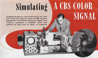
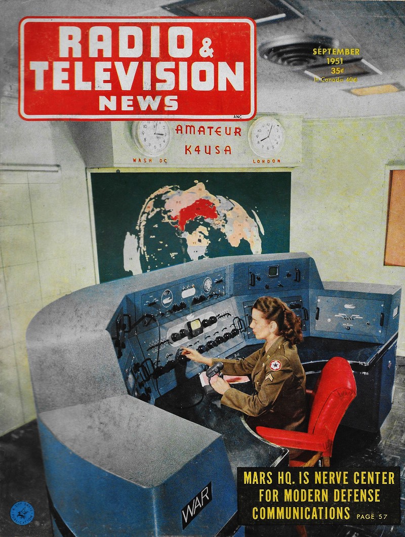
Fig. 1 - Complete set-up of equipment used in color demonstration
presented at the Radio Electronics School of New York.
By Murray Barlowe
Color Development Eng., Tele-King Television Corp.
The decision by the FCC to adopt the CBS color system was the spark that set
off the biggest controversy that the radio-television field has experienced in years.
An overwhelming demand for information about color television, both by the public
and the technician, resulted. It was in response to this demand that the author,
with the full cooperation of the staff of the Radio Electronics School, set up a
series of public demonstrations and lectures on color television.
Since CBS was not transmitting color signals at the time, the problem was solved
by constructing a "flying spot scanner" (Fig. 8) to take the place of the color
camera.
Basically, the equipment consists of a high intensity CRT with its associated
high voltage power supply and deflection circuits, a photoelectric pick-up tube,
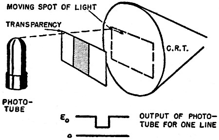
and a high gain video amplifier. The picture to be transmitted is in the form of
a transparency which is placed on the face of the CRT. The raster on the face of
the CRT is produced by a rapidly moving spot of light. At anyone instant, only one
spot on the face of the CRT is giving off light. This spot of light passes through
the transparency and falls on the photoelectric pickup tube. The phototube converts
the light into an electrical voltage proportional to the intensity of the light.
As the spot of light moves across the tube, the amount reaching the phototube will
increase or decrease, depending upon the density of the different parts of the transparency.
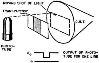
Fig. 2 - Intensity of the light from the moving spot, impinging
on phototube varies with any change in transparency density.

Fig. 3 - To obtain color signal, a color transparency and disc
are inserted as shown.
Editor's Note: This set-up was originally used as a closed-circuit
system for demonstrating color television. From the ideas presented it is possible
for manufacturers or service organizations who are doing work on color receivers
to build a test unit so that work can continue even in the absence of on-the-air
CBS signals. For additional details on constructing a flying spot scanner, see J.
R. Popkin-Clurman's article "Simplified Ham TV Station" appearing in the May, June,
and July 1950 issues of this magazine.
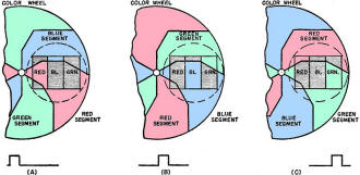
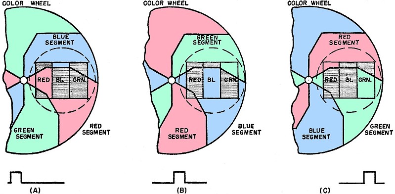
Fig. 4 - Scanning sequence. Output of phototube is shown in (A)
for red, (B) for blue, and (C) for green. Color disc rotates at a speed of 1440
revolutions per minute.
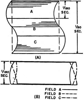
Fig. 5 - Curvature caused by a 60-cycle magnetic field when operating
at 180 field/sec.
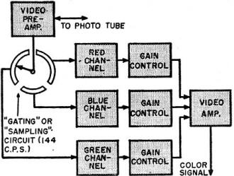
Fig. 6 - Block diagram showing how gated circuit is used to select
the proper channel.

Fig. 9 - An example of the curvature of the vertical edges of
the raster caused by (A) 60 cycle and (B) 120 cycle interference.

Fig. 10 - Provision must be made for rotation of the motor in
order to obtain the proper color phasing at the TV receiver.
As each line is scanned, a voltage is generated by the phototube which varies
in amplitude directly as the light and dark variations on the transparency, Fig.
2. The output of the photo tube is amplified and is the video signal containing
all of the picture information. To adapt this principle to produce a color video
signal, a color transparency is used in place of the black and white transparency
and a color filter wheel is inserted between the transparency and the phototube.
See Fig, 3. A simple color transparency, consisting of three vertical bands of color,
will be used in place of a full color picture in our analysis of how the system
works. As the spot of light moves across the first line from left to right, a section
of the color filter wheel moves between the transparency and the photo tube. Assuming
the first section to be a red filter, which will allow only red light to pass through,
the output of the phototube will increase when the spot of light passes through
the vertical red strip in the beginning of each line, as indicated in Figs. 4A and
4B. Each filter section of the color wheel will be between the transparency and
the photo tube for the time required for the light spot to scan an entire field.
For a color signal co-forming to the CBS standards, this time interval would be
1/144th of a second. During this interval, all of the red portions of a color image
will pass through the color filter and produce a video signal representing the red
image. At the start of the next field, the spot of light will be in the upper left
hand corner and a blue section of the color wheel will now be coming into place.
It will only allow the blue light to pass through and so the video signal produced
during this field will represent the blue image. Next, the green filter comes into
place and the process is repeated, producing the green video signal. In practice,
a full color transparency takes the place of the three vertical color bars and the
video signals produced during each field would have a more complex waveform.
The output of the video amplifier is applied to the grid of the CRT in a TV receiver.
Sync pulses from the sweep circuits of the flying spot scanner are used to synchronize
the sweep circuits of the receiver. During each field a picture is produced on the
face of the CRT which is a black and white version of the primary color image being
scanned at the time. If we look at this black and white image during the red field
through a red filter, we would see a true reproduction of the red information in
the transparency. The red filter tints the black and white image to its correct
color. By using a color filter wheel at the receiver similar to the one at the flying
spot scanner, and having it rotate in synchronism, the full color images are first
separated into their primary colors, transmitted as black and white versions of
the primary colors, tinted by the color wheel at the, receiver, and reproduced in
full color.
In the CBS system, the color fields are scanned at the rate of 144 per second.
A color wheel containing six color filter segments, two each of the three primary
colors, is rotated at a speed of 1440 revolutions per minute by a synchronous motor.
(Since 1440 rpm synchronous motors are not available, an 1800 rpm motor with a 4
to 5 speed reduction is used to obtain the required speed of 1440 rpm.) This is
equivalent to 24 revolutions per second. Since there are six equal segments in the
wheel, the time required for a single segment to pass a given point would be one
sixth of a 24th of a second, or a 1/144th of a second. This is the time required
for a single color field.
By using a horizontal sweep frequency of 29,160 cps, interlaced at 144 fields
per second, a 405 line picture is produced.
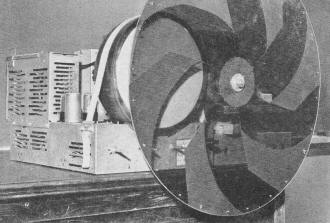
Fig. 7 - Over-all view of the color receiver used by author in
his simulated CBS color system. The color wheel consists of twelve segments with
every other segment opaque. The sequence is red color filter, opaque segment, blue
filter, opaque segment, green filter, opaque segment. etc., with a total of six
color filter segments and six opaque segments. In developing the shape of the color
filter segments it was apparent that light from the CRT did not pass through every
part of the wheel but rather through "half moon" shaped areas. Since this was the
case. it was not necessary for the wheel to be entirely transparent. Balance weights
and metal strips used for generating the reference sync pulse were mounted on the
opaque or unused areas. Opaque segments were finally deemed unnecessary and eliminated
on later models.
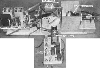
Fig. 8 - Over-all view of flying spot scanner.
More than the usual amount of power supply filtering was necessary. This is a
problem that technicians making color conversions of transmitting or receiving equipment
will have to contend with. In the present black and white system using 60 fields
per second, hum in the horizontal deflection circuits could cause the vertical sides
of the raster to have a slight curvature as illustrated in Figs. 9A and 9B. This
hum may be due to magnetic fields (60 cycle) from the power transformer or to the
120 cycle ripple due to insufficient filtering in the power supply. This curvature
is hardly noticeable when the vertical sweep frequency is 60 cps, At sweep frequencies
of 144 or 180 per second, the visible effect becomes serious. Figs. 5A and 5B illustrate
the effect (intentionally exaggerated) when the interference is from a 60 cycle
magnetic field and the equipment is operating at 180 fields per second. Three fields
would occur in the time previously required for one field. Superimposing the three
fields, as they would appear on the face of the CRT, it becomes apparent that they
are displaced with respect to each other. This makes it impossible for the three
colors to "register" properly, producing a picture that is constantly shimmering,
and one which has very poor detail.
To keep this from happening it is necessary to thoroughly filter the "B" supply,
and protect the CRT against the influence of stray magnetic fields. A mu-metal shield
around the picture tube and a heavy copper band around the power transformer are
some of the possible solutions to the problem.
Color Balance
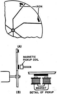
Fig. 11 - Mechanical details of synchronizing system. Six pieces
of soft iron are fastened to outside edge of color disc.
The spectral response of the 931A phototube used as the pickup device drops off
rapidly at the red end of the spectrum. To correct this, a thin sheet of very lightly
tinted red acetate was permanently fastened to the face of the CRT used in the flying
spot scanner. This cut down the intensity of light of the colors other than red
to compensate for the lack of sensitivity of the phototube to red. A better method
might be to use two or more 931A phototubes feeding the video amplifier with a red
color filter permanently mounted in front of one tube thus making it sensitive only
to red light. This would boost the level of the video signal produced by the red
image. Our equipment is presently being modified to include a "gating" circuit operating
at the field frequency which will switch the output of the phototube to a separate
video amplifier every time a different color filter segment of the color wheel comes
into place (Fig. 6). This will connect the video signal out-put of the phototube
to the red video amplifier for the duration of the red field. Immediately after
the red field the signal is switched to the blue video amplifier for the duration
of the blue field, and finally to the green video amplifier for the duration of
the green field. By adjusting the gain of the video amplifier for- each color channel,
the relative amplitudes of the color signals can be properly balanced.
Synchronizing the System
Proper sync and phasing of the complete system is accomplished in the following
manner. Six thin pieces of soft iron are fastened along the outside edge of the
color wheel at the flying spot scanner (Fig. 11). The pickup coil from a magnetic
phonograph pickup is mounted close to the edge of the wheel. As the iron segments
move past the pickup coil, a pulse is produced. Since there is a piece of iron for
every color segment, the output of the pickup coil will be a series of pulses at
the field frequency. These pulses are used to synchronize the vertical sweep circuits
and thereby control the timing of the entire system. A phase shifting network is
connected between the magnetic pickup coil and the vertical sweep generator. By
adjusting this control the start of each field can be varied with respect to the
position of the color wheel. Once set, this control usually doesn't have to be readjusted,
unless the position of the pickup coil is changed.
Color phasing at the receiver is accomplished by mounting the motor which rotates
the color wheel so that it can be rotated through approximately 160 degrees, as
illustrated in Fig. 10. The motor is rotated until the segment of the color test
pattern marked "blue" becomes blue.
Posted August 17, 2020
Color and Monochrome (B&W) Television
Articles
|