|
[Go to TOC] ALTERNATE TWO-WAY RADAR EQUATION
In this section the same radar equation factors are grouped differently to create different constants as is used by some authors.
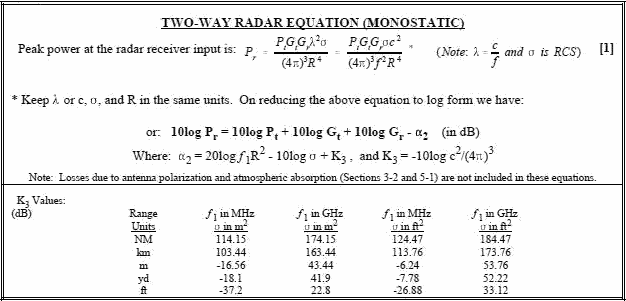
In the last section, we had the basic radar equation given as equation [6] and it is repeated as equation [1] in the table below.
In section 4-4, in order to maintain the concept and use of the one-way space loss coefficient, α1
, we didn't cancel like terms which was done to form equation [6] there. Rather, we regrouped the factors of equation [5]. This resulted in
two minus α1 terms and we defined the remaining term as Gσ, which accounted for RCS (see equation
[8] & [9]). 
Some authors take a different approach, and instead develop an entirely new single factor α2
, which is used instead of the combination of α1 and Gσ. If equation [1] is reduced
to log form, (and noting that f = c/λ) it becomes: 10log Pr = 10log Pt + 10log Gt + 10log Gr
- 20log (fR2) + 10log σ + 10log (c2/(4π)3) [2]
We now call the last three terms on the right minus α2 and use it as a single term instead of
the two terms α1 and Gσ. The concept of dealing with one variable factor may be easier although
we still need to know the range, frequency and radar cross section to evaluate α2. Additionally, we can
no longer use a nomograph like we did in computing α1 and visualize a two-way space loss consisting of
two times the one-way space loss, since there are now 3 variables vs two. Equation [2] reduces to: 10log Pr = 10log Pt + 10log Gt + 10log
Gr - "2 (in dB) [3] Where α2 = 20log (f1R2)
- 10log σ + K3 and where f1 is the MHz or GHz value of frequency and K3 = -10log (c2/(4π)3) + 20log (conversion for Hz to MHz or GHz)+ 40log (range unit conversions if not in meters) - 20log (RCS
conversions for meters to feet) The values of K3 are given in the table above. Comparing equation [3] to equation [10]
in Section 4-4, it can be seen that α2 = 2α1 - Gσ.
Table of Contents for Electronics Warfare and Radar Engineering Handbook
Introduction |
Abbreviations | Decibel | Duty
Cycle | Doppler Shift | Radar Horizon / Line
of Sight | Propagation Time / Resolution | Modulation
| Transforms / Wavelets | Antenna Introduction
/ Basics | Polarization | Radiation Patterns |
Frequency / Phase Effects of Antennas |
Antenna Near Field | Radiation Hazards |
Power Density | One-Way Radar Equation / RF Propagation
| Two-Way Radar Equation (Monostatic) |
Alternate Two-Way Radar Equation |
Two-Way Radar Equation (Bistatic) |
Jamming to Signal (J/S) Ratio - Constant Power [Saturated] Jamming
| Support Jamming | Radar Cross Section (RCS) |
Emission Control (EMCON) | RF Atmospheric
Absorption / Ducting | Receiver Sensitivity / Noise |
Receiver Types and Characteristics |
General Radar Display Types |
IFF - Identification - Friend or Foe | Receiver
Tests | Signal Sorting Methods and Direction Finding |
Voltage Standing Wave Ratio (VSWR) / Reflection Coefficient / Return
Loss / Mismatch Loss | Microwave Coaxial Connectors |
Power Dividers/Combiner and Directional Couplers |
Attenuators / Filters / DC Blocks |
Terminations / Dummy Loads | Circulators
and Diplexers | Mixers and Frequency Discriminators |
Detectors | Microwave Measurements |
Microwave Waveguides and Coaxial Cable |
Electro-Optics | Laser Safety |
Mach Number and Airspeed vs. Altitude Mach Number |
EMP/ Aircraft Dimensions | Data Busses | RS-232 Interface
| RS-422 Balanced Voltage Interface | RS-485 Interface |
IEEE-488 Interface Bus (HP-IB/GP-IB) | MIL-STD-1553 &
1773 Data Bus | This HTML version may be printed but not reproduced on websites.
|


