|
[Go to TOC]
IFF - IDENTIFICATION - FRIEND OR FOE
Originated in WWII for just that purpose - a way for our secondary radars to identify U.S. aircraft from
enemy aircraft by assigning a unique identifier code to U.S. aircraft transponders. The system is
considered a secondary radar system since it operates completely differently and independently of the primary
radar system that tracks aircraft skin returns only, although the same CRT display is frequently used for both.
The system was initially intended to distinguish between enemy and friend but has evolved such that the term "IFF"
commonly refers to all modes of operation, including civil and foreign aircraft use. There are four major
modes of operation currently in use by military aircraft plus one submode.
- Mode 1 is a nonsecure low cost method used by ships to track aircraft and other ships.
- Mode 2 is used by aircraft to make carrier controlled approaches to ships during inclement weather.
- Mode 3 is the standard system also used by commercial aircraft to relay their position to ground
controllers throughout the world for air traffic control (ATC).
- Mode 4 is secure encrypted IFF (the only true method of determining friend or foe)
- Mode "C" is the altitude encoder.
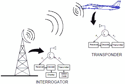
The non-secure codes are manually set by the pilot but assigned by the air traffic controller.A cross-band
beacon is used, which simply means that the interrogation pulses are at one frequency and the reply pulses are at
a different frequency. 1030 MHz and 1090 MHz is a popular frequency pair used in the U.S. The secondary
radar transmits a series of selectable coded pulses. The aircraft transponder receives and decodes the
interrogation pulses. If the interrogation code is correct, the aircraft transponder transmits a different series
of coded pulses as a reply.
The advantage of the transponder is that the coded pulses "squawked" by the aircraft transponders after being
interrogated might typically be transmitted at a 10 watt ERP, which is much stronger than the microwatt skin
return to the primary radar. Input power levels may be on the order of several hundred watts. The
transponder antenna is low gain so that it can receive and reply to a radar from any direction. An adjunct to
the IFF beacon is the altitude encoding transponder known as mode C - all commercial and military aircraft have
them, but a fair percentage of general aviation light aircraft do not because of cost. The number of transponder
installations rises around many large metropolitan areas where they are required for safety (easier identification
of aircraft radar tracks).
Air traffic control primary radars are similar to the two dimensional search radar (working in azimuth and
range only) and cannot measure altitude. The expanded display in figure 1 is typical of an air traffic
control IFF response. The aircraft was told to squawk a four digit number such as "4732". The altitude encoded
transponder provides the aircraft altitude readout to the ground controllers display along with the coded response
identifying that particular aircraft.
 Figure 1. IFF
Transponder
Note: The radar I worked on in the USAF sported a
TPX-42 IFF systems. Some
of its components, including the "Tootsie Roll" antenna on top of the shelter and the equipment rack inside, can
be seen in the pictures on my 5CCG radar shop page.
Table of Contents for Electronics Warfare and Radar Engineering Handbook
Introduction |
Abbreviations | Decibel | Duty
Cycle | Doppler Shift | Radar Horizon / Line
of Sight | Propagation Time / Resolution | Modulation
| Transforms / Wavelets | Antenna Introduction
/ Basics | Polarization | Radiation Patterns |
Frequency / Phase Effects of Antennas |
Antenna Near Field | Radiation Hazards |
Power Density | One-Way Radar Equation / RF Propagation
| Two-Way Radar Equation (Monostatic) |
Alternate Two-Way Radar Equation |
Two-Way Radar Equation (Bistatic) |
Jamming to Signal (J/S) Ratio - Constant Power [Saturated] Jamming
| Support Jamming | Radar Cross Section (RCS) |
Emission Control (EMCON) | RF Atmospheric
Absorption / Ducting | Receiver Sensitivity / Noise |
Receiver Types and Characteristics |
General Radar Display Types |
IFF - Identification - Friend or Foe | Receiver
Tests | Signal Sorting Methods and Direction Finding |
Voltage Standing Wave Ratio (VSWR) / Reflection Coefficient / Return
Loss / Mismatch Loss | Microwave Coaxial Connectors |
Power Dividers/Combiner and Directional Couplers |
Attenuators / Filters / DC Blocks |
Terminations / Dummy Loads | Circulators
and Diplexers | Mixers and Frequency Discriminators |
Detectors | Microwave Measurements |
Microwave Waveguides and Coaxial Cable |
Electro-Optics | Laser Safety |
Mach Number and Airspeed vs. Altitude Mach Number |
EMP/ Aircraft Dimensions | Data Busses | RS-232 Interface
| RS-422 Balanced Voltage Interface | RS-485 Interface |
IEEE-488 Interface Bus (HP-IB/GP-IB) | MIL-STD-1553 &
1773 Data Bus | This HTML version may be printed but not reproduced on websites.
Related Pages on RF Cafe
-
Introduction to Radar (Air University)
- Radar Equation, 2-Way
(another)
-
Radar Equation, 1-Way
-
Radar Equation, Bistatic
-
Radar Techniques - Primer (1945 QST)
- Radar
Postage Stamps
- RF Cafe Quiz #7 - Radar Principles
- AN/MPN-14 USAF Radar Shop
- AN/TPN-19 USAF Radar Shop
- USAF Radar Shop E-Mails
- EW/Radar
Handbook - Doppler Shift
- Doppler Shift Calculator
-
Identification Friend or Foe (IFF)
-
Radar Horizon / Line of Sight
- Radar Systems Vendors
-
NEETS Radar Principles
- Radar System Vendors
- Who Invented Radar?
-
Simple Modification Increases ATC Reliability
|


