|
[Go to TOC] GENERAL RADAR DISPLAY TYPES
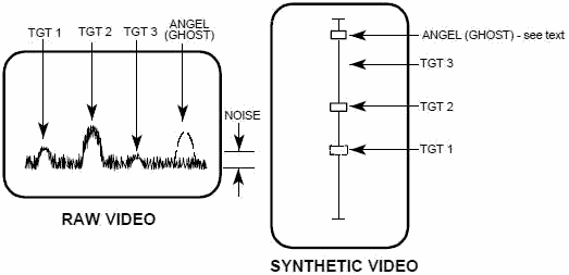
There are two types of radar displays in common use today. RAW VIDEO Raw video
displays are simply oscilloscopes that display the detected and amplified target return signal (and the receiver
noise). Raw video displays require a human operator to interpret the various target noise and clutter signals.
On the left hand display of Figure 1, an operator could readily identify three targets and a ghost (a ghost is a
phony target that usually fades in and out and could be caused by birds, weather, or odd temporary reflections -
also referred to as an angel). Target 3 is a weak return and hidden in the noise - an operator can identify it as
a target by the "mouse under the rug" effect of raising the noise base line. SYNTHETIC VIDEO
Synthetic video displays use a computer to clean up the display by eliminating noise and clutter and creating it's
own precise symbol for each target. On the right hand display target 1 comes and goes because it is barely
above the receiver noise level - notice that it is quite clear on the raw video. Target 3 wasn't recognized by the
computer because it's to far down in the noise. The computer validated the ghost as a target. The ghost might be a
real target with glint or ECM characteristics that were recognized by the computer but not the operator.

Figure 1. Radar Display Types
SEARCH AND ACQUISITION RADARS They generally use either a PPI or a sector PPI
display as shown in Figure 2. PPI displays can be either raw video or synthetic video. PPI scope (plan
position indicator). Polar plot of direction and distance. Displays all targets for 360 degrees.
Sector PPI scope. Polar plot of direction and distance. Displays all targets within a
specific sector. Origin may be offset so that "your" radar position may be off the scope.
TRACKING RADARS Usually use some combination of A, B, C, or E scope displays. There are many other
types of displays that have been used at one time or another - including meters - but those listed here are the
most common in use today.

Figure 2. Common Radar Displays
A-SCOPE Target signal amplitude vs. range or velocity. Displays all targets along
pencil beam for selected range limits. Displays tracking gate. Usually raw video. Some modern radars have
raw video a-scopes as an adjunct to synthetic video displays. Must be used with a separate azimuth and
elevation display of some sort. Also called a range scope (R-Scope). B-SCOPE
Range vs. azimuth or elevation. Displays targets within selected limits. Displays tracking gate. May be raw
or synthetic video. Surface radars usually have two. One azimuth/one elevation which can result in
confusion with multiple targets. C-SCOPE Azimuth vs. elevation. Displays
targets within selected limits of az and el. Displays tracking gate. May display bull's-eye or aim dot.
May have range indicator inserted typically as a marker along one side. Usually synthetic video.
Pilots eye view and very common in modern fighter aircraft heads up displays for target being tracked.
Could be used in any application where radar operator needs an "aiming" or "cross hair" view like a rifle scope.
E-SCOPE Elevation vs. Range similar to a B-scope, with elevation replacing
Table of Contents for Electronics Warfare and Radar Engineering Handbook
Introduction |
Abbreviations | Decibel | Duty
Cycle | Doppler Shift | Radar Horizon / Line
of Sight | Propagation Time / Resolution | Modulation
| Transforms / Wavelets | Antenna Introduction
/ Basics | Polarization | Radiation Patterns |
Frequency / Phase Effects of Antennas |
Antenna Near Field | Radiation Hazards |
Power Density | One-Way Radar Equation / RF Propagation
| Two-Way Radar Equation (Monostatic) |
Alternate Two-Way Radar Equation |
Two-Way Radar Equation (Bistatic) |
Jamming to Signal (J/S) Ratio - Constant Power [Saturated] Jamming
| Support Jamming | Radar Cross Section (RCS) |
Emission Control (EMCON) | RF Atmospheric
Absorption / Ducting | Receiver Sensitivity / Noise |
Receiver Types and Characteristics |
General Radar Display Types |
IFF - Identification - Friend or Foe | Receiver
Tests | Signal Sorting Methods and Direction Finding |
Voltage Standing Wave Ratio (VSWR) / Reflection Coefficient / Return
Loss / Mismatch Loss | Microwave Coaxial Connectors |
Power Dividers/Combiner and Directional Couplers |
Attenuators / Filters / DC Blocks |
Terminations / Dummy Loads | Circulators
and Diplexers | Mixers and Frequency Discriminators |
Detectors | Microwave Measurements |
Microwave Waveguides and Coaxial Cable |
Electro-Optics | Laser Safety |
Mach Number and Airspeed vs. Altitude Mach Number |
EMP/ Aircraft Dimensions | Data Busses | RS-232 Interface
| RS-422 Balanced Voltage Interface | RS-485 Interface |
IEEE-488 Interface Bus (HP-IB/GP-IB) | MIL-STD-1553 &
1773 Data Bus | This HTML version may be printed but not reproduced on websites.
Related Pages on RF Cafe
-
Introduction to Radar (Air University)
- Radar Equation, 2-Way
(another)
-
Radar Equation, 1-Way
-
Radar Equation, Bistatic
-
Radar Techniques - Primer (1945 QST)
- Radar
Postage Stamps
- RF Cafe Quiz #7 - Radar Principles
- AN/MPN-14 USAF Radar Shop
- AN/TPN-19 USAF Radar Shop
- USAF Radar Shop E-Mails
- EW/Radar
Handbook - Doppler Shift
- Doppler Shift Calculator
-
Identification Friend or Foe (IFF)
-
Radar Horizon / Line of Sight
- Radar Systems Vendors
-
NEETS Radar Principles
- Radar System Vendors
- Who Invented Radar?
-
Simple Modification Increases ATC Reliability
|


