|
March 1965 Popular Electronics
 Table of Contents
Wax nostalgic about and learn from the history of early electronics. See articles
from
Popular Electronics,
published October 1954 - April 1985. All copyrights are hereby acknowledged.
|
Just yesterday I posted
an article titled "Understanding
Your Triggered Sweep Scope," that appeared in the May 1973 issue of Popular
Electronics, so I figured this "Scope-Trace Quiz" would make a good compliment.
It is from a 1965 issue of Popular Electronics. Driver circuits all include
a sinewave source in parallel with a series resistor and diode, connected to the
vertical and horizontal o-scope inputs. The resulting Lissajous waveforms resemble
hands on a clock face thanks to the diode. Shamefully, I only scored 70%, but in
my own defense I'll say I didn't take the time to draw them out on paper. Pay careful
attention to the scope connections. There was another
o-scope quiz
in 1961.
Scope-Trace Quiz
 By Robert P. Balin By Robert P. Balin
How are you at vectors? Here's a chance to get some practice and test your scope
sense. The vertical and horizontal input signals to an oscilloscope combine to form
Lissajous patterns whose appearance depends on the waveform, frequency, and relative
phase of the two signals. Knowing how these patterns are formed will help you to
interpret waveforms and to have a better understanding of the scope. Test your ability
to project (vectorially) the forces at work on the electron beam in the CRT. Six
different oscilloscope traces are shown in A-F. Can you match them with circuits
1-6 below?
 The resistor used in each circuit has a
value equal to the reverse resistance of the diode. Forward resistance of the diode
is negligible. The circuits shown do not load or distort the signal source. Both
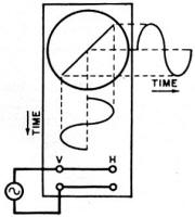
the vertical and horizontal gain controls have been set to provide equal gain. Positive-going
signals cause the beam to be deflected upward for the vertical input and to the
right for the horizontal input, The example at left shows the resultant trace derived
from the same signal applied to both the vertical and horizontal scope inputs. Tips
on how to solve this quiz appear with the answers (at bottom of page). The resistor used in each circuit has a
value equal to the reverse resistance of the diode. Forward resistance of the diode
is negligible. The circuits shown do not load or distort the signal source. Both
the vertical and horizontal gain controls have been set to provide equal gain. Positive-going
signals cause the beam to be deflected upward for the vertical input and to the
right for the horizontal input, The example at left shows the resultant trace derived
from the same signal applied to both the vertical and horizontal scope inputs. Tips
on how to solve this quiz appear with the answers (at bottom of page).
See answers below.
Quizzes from vintage electronics magazines (and many custom RF Cafe-generated
quizzes) such as Popular Electronics, Electronics-World,
QST, Radio-Electronics, and Radio News were published
over the years - some really simple and others not so simple. Robert P. Balin
created most of the quizzes for Popular Electronics. This is a listing
of all I have posted thus far.
- Oscillator
Quiz, November 1962 Popular Electronics
- Vacuum Tube Quiz,
February 1961 Popular Electronics
- Kool-Keeping Kwiz, June
1970 Popular Electronics
- Find the Brightest
Bulb Quiz, April 1960 Popular Electronics
-
Where Do the Scientists Belong? - Feb 19, 1949 Saturday Evening Post
- Quiz
on AC Circuit Theory, December 1970 Popular Electronics
- Magnetic
Phenomena Quiz, February 1962 Popular Electronics
- Electronics
Geography Quiz, April 1970 Popular Electronics
- Electronic
Menu Quiz, August 1963 Popular Electronics
- Electronic
Noise Quiz, August 1962 Popular Electronics
- Electronic
Current Quiz, October 1963 Popular Electronics
- Electronic
Inventors Quiz, November 1963 Popular Electronics
- Resistor Function
Quiz, January 1962 Popular Electronics
- Electronic
Measurement Quiz, January 1963 Popular Electronics
- Electronic
Coupling Quiz, August 1973 Popular Electronics
- Electronics
Analogy Quiz, August 1960 Popular Electronics
- Audio Quiz, April
1955 Popular Electronics
- Electronic Unit
Quiz, May 1962 Popular Electronics
- Capacitor
Circuit Quiz, June 1968 Popular Electronics
- Meter-Reading
Quiz, June 1966 Popular Electronics
- Electronic
Geometry Quiz, Jan 1965 Popular Electronics
- Electronic
Factor Quiz, November 1966 Popular Electronics
- Electronics
Math Quiz, November 1965 Popular Electronics
- Series Circuit
Quiz, May 1966 Popular Electronics
- Electrochemistry
Quiz, Mar 1966 Popular Electronics
- Biz
Quiz: Test Your Sales Ability - April 1947 Radio News
- Electronic
Analogy Quiz, Nov 1961 Popular Electronics
- Diode Quiz, July
1961 Popular Electronics
- Electronic
Curves Quiz, Feb 1963 Popular Electronics
- Electronic
Numbers Quiz, Dec 1962 Popular Electronics
- Energy Conversion
Quiz, April 1963 Popular Electronics
- Coil Function
Quiz, June 1962 Popular Electronics
-
Co-Inventors Quiz - January 1965 Electronics World
-
"-Tron" Teasers Quiz - Oct 1963 Electronics World
- Polarity Quiz
- March 1968 Popular Electronics
-
Television
I.Q. Quiz - Oct 1948 Radio & Television News
- Amplifier Quiz
Part I - Feb 1964 Popular Electronics
- Semiconductor
Quiz - Feb 1967 Popular Electronics
- Unknown
Frequency Quiz - September 1965 Popular Electronics
- Electronics
Metals Quiz - Oct 1964 Popular Electronics
- Electronics
Measurement Quiz - August 1967 Popular Electronics
- Vector-Circuit
Matching Quiz, June 1970 Popular Electronics
- Inductance
Quiz, September 1961 Popular Electronics
- RC Circuit Quiz,
June 1963 Popular Electronics
|
-
LCR Circuits Quiz - November 1969 Electronics World
- Amplifier Quiz Part
2 - March 1964 Popular Electronics
- Amplifier Quiz
Part 1 - February 1964 Popular Electronics
- Three Letter
Quiz - January 1964 Popular Electronics
- Electromagnetic
Function - June 1964 Popular Electronics
- Electronic
Sticklers - February 1959 Popular Electronics
- Bio-Electronic
Quiz - July 1964 Popular Electronics
- Transformer Quiz
- April 1962 Popular Electronics
- Oscilloscope
Quiz - October 1961 Popular Electronics
- Roundword Puzzle
- January 1961 Popular Electronics
- Electronic
Sticklers - April 1959 Popular Electronics
-
What's Your EQ? - August 1966 Radio-Electronics
-
What's Your EQ? - February 1966 Radio-Electronics
-
What's Your EQ? - September 1962 Radio-Electronics
- Electronic Sticklers
- May 1959 Popular Electronics
-
What's Your EQ? - February 1963 Radio-Electronics
-
What's Your EQ? - April 1964 Radio-Electronics
-
What's Your EQ? - October 1966 Radio-Electronics
-
What's Your EQ? - June 1963 Radio-Electronics
-
What's Your EQ? - July 1966 Radio-Electronics
-
What's Your EQ? - December 1966 Radio-Electronics
-
What's Your EQ? - October 1964 Radio-Electronics
-
What's Your EQ? - July 1963 Radio-Electronics
-
What's Your EQ? - March 1966 Radio-Electronics
-
What's Your EQ? - November 1966 Radio-Electronics
-
What's Your EQ? - October 1966 Radio-Electronics
-
What's Your EQ? - May 1966 Radio-Electronics
-
What's Your EQ? - January 1966 Radio-Electronics
-
What's Your EQ - July 1966 Radio-Electronics
-
What's Your EQ? - December 1966 Radio-Electronics
-
What's Your EQ? - October 1964 Radio-Electronics
-
What's Your EQ? - June 1963 Radio-Electronics
-
R-E Puzzler - June 1967 Radio-Electronics
-
What's Your EQ? - January 1963 Radio-Electronics
-
Do You Know the Law? - Nov 1963 Radio-Electronics
-
What's Your EQ? - November 1962 Radio-Electronics
-
What's Your EQ? - September 1966 Radio-Electronics
- Radio
WittiQuiz - October 1938 Radio-Craft
-
What's Your EQ? - November 1964 Radio-Electronics
-
What's Your EQ? - February 1964 Radio-Electronics
-
What's Your EQ? - July 1967 Radio-Electronics
-
What's Your EQ? - December 1962 Radio-Electronics
-
What's Your EQ? - April 1966 Radio-Electronics
-
What's Your EQ? - October 1963 Radio-Electronics
-
What's Your EQ? - July 1964 Radio-Electronics
- Radio
WittiQuiz - November 1937 Radio-Craft
-
What's Your EQ? - May 1967 Radio-Electronics
-
What's Your EQ? - July 1962 Radio-Electronics
-
What's Your EQ? - January 1962 Radio-Electronics
-
What's Your EQ? - February 1962 Radio-Electronics
-
What's Your EQ? - March 1962 Radio-Electronics
-
What's Your EQ? - July 1961 Radio-Electronics
-
What's Your EQ? - August 1961 Radio-Electronics
-
Can You Name These Strange Electronic Effects? - August 1962 Radio-Electronics
-
What's Your EQ? - September 1961 Radio-Electronics
-
What's Your EQ? - September 1962 Radio-Electronics
-
What's Your EQ? - October 1961 Radio-Electronics
- Radio
WittiQuiz - December 1937 Radio-Craft
-
What's Your EQ? - November 1961 Radio-Electronics
-
What's Your EQ? - March 1964 Radio-Electronics
-
What's Your EQ? - April 1962 Radio-Electronics
-
What's Your EQ? - May 1962 Radio-Electronics
-
What's Your EQ? - June 1962 Radio-Electronics
-
What's Your EQ? - April 1967 Radio-Electronics
-
What's Your EQ? - March 1967 Radio-Electronics
-
What's Your EQ? - December 1964 Radio-Electronics
-
What's Your EQ? - January 1967 Radio-Electronics
-
Wanted: 50,000 Engineers - Jan 1953 Popular Mechanics
-
What's Your EQ? - August 1964 Radio-Electronics
- Voltage Quiz
- December 1961 Popular Electronics
-
What is It? - June 1941 Popular Science
- What Do You Know
About Resistors? - April 1974 Popular Electronics
-
What's Your EQ? - September 1963 Radio-Electronics
- Potentiometer Quiz - Sep
1962 Popular Electronics
-
Mathematical Bafflers - March 1965 Mechanix Illustrated
- Op Amp Quiz -
October 1968 Popular Electronics
- Electronic "A"
Quiz - April 1968 Popular Electronics
-
What's Your EQ? - May 1961 Radio-Electronics
-
Popular Science Question Bee - Feb 1939 Popular Science
-
What is It? - A Question Bee in Photographs - June 1941 Popular Science
-
What's Your EQ? - June 1961 Radio-Electronics
-
What's Your EQ? - June 1964 Radio-Electronics
-
What's Your EQ? - May 1964 Radio-Electronics
-
What's Your EQ? - August 1963 Radio-Electronics
-
What's Your EQ? - May 1963 Radio-Electronics
- Bridge
Function Quiz - Sep 1969 Radio-Electronics
-
What's Your EQ? - March 1963 Radio-Electronics
-
What's Your EQ? - February 1967 Radio-Electronics
-
Circuit Quiz - June 1966 Radio-Electronics
-
What's Your EQ? - June 1966 Radio-Electronics
- Electronics
Mathematics Quiz - June 1969 Popular Electronics
- Brightest
Light Quiz - April 1964 Popular Electronics
-
What's Your EQ? - April 1963 Radio-Electronics
- Electronics "B" Quiz
- July 1969 Popular Electronics
- Ohm's Law Quiz
- March 1969 Popular Electronics
-
Antenna Quiz - November 1962 Electronics World
- Color Code Quiz
- November 1967 Popular Electronics
- CapaciQuiz
- August 1961 Popular Electronics
- Transformer
Winding Quiz - Dec 1964 Popular Electronics
-
Audiophile Quiz - November 1957 Radio-electronics
- Capacitor
Function Quiz - Mar 1962 Popular Electronics
- Greek Alphabet
Quiz - December 1963 Popular Electronics
- Circuit
Designer's Name Quiz - July 1968 Popular Electronics
-
Sawtooth Sticklers Quiz - Nov 1960 Radio-Electronics
-
Elementary
Radio Quiz - December 1947 Radio-Craft
- Hi-Fi
Quiz - October 1955 Radio & Television News
- Electronics Physics
Quiz - March 1974 Popular Electronics
- A Baffling Quiz
- January 1968 Popular Electronics
- Electronics IQ
Quiz - May 1967 Popular Electronics
- Plug and Jack
Quiz - Dec 1967 Popular Electronics
- Electronic
Switching Quiz - Oct 1967 Popular Electronics
- Electronic
Angle Quiz - Sep 1967 Popular Electronics
- International
Electronics Quiz - July 1967 Popular Electronics
- FM Radio
Quiz - April 1950 Radio & Television News
- Bridge Circuit
Quiz -Dec 1966 Popular Electronics
- Diode Function
Quiz - August 1965 Popular Electronics
- Diagram Quiz,
August 1966 Popular Electronics
- Quist Quiz - November
1953 QST
- TV Trouble Quiz,
July 1966 Popular Electronics
- Electronics History Quiz,
Dec 1965 Popular Electronics
- Scope-Trace Quiz,
March 1965 Popular Electronics
-
Electronic
Circuit Analogy Quiz, April 1973
-
Test Your Knowledge of Semiconductors, August 1972 Popular Electronics
- Ganged Switching
Quiz, April 1972 Popular Electronics
- Lamp Brightness
Quiz, Jan 1969 Popular Electronics
- Lissajous
Pattern Quiz, Sep 1963 Popular Electronics
- Electronic
Quizoo, October 1962 Popular Electronics
- Electronic
Photo Album Quiz, March 1963 Popular Electronics
- Electronic
Alphabet Quiz, May 1963 Popular Electronics
- Quiz: Resistive?
Inductive? or Capacitive?, October 1960 Popular Electronics
|
Scope-Trace Quiz Answers
 If you had trouble solving this quiz, consider
the following facts: If you had trouble solving this quiz, consider
the following facts:
(1) Output across the complete resistor and diode circuit is the same amplitude
as the input signal.
(2) Output across the resistor only varies between 50% and 100% (100% when the
diode is working in the forward direction).
(3) Output across the diode varies between 50% and 0% (0% when the diode is working
in the forward direction).
|


