|
March 1964 Radio-Electronics
 [Table of Contents] [Table of Contents]
Wax nostalgic about and learn from the history of early electronics.
See articles from Radio-Electronics,
published 1930-1988. All copyrights hereby acknowledged.
|
Seeing a reader name of Qutaiba Bassim El-Dhuwaib
would not seem unusual in one of today's technical magazines, but having it
appear in a 1964 issue of Radio-Electronics was definitely a rarity.
Such was the case with this first "Black Box" circuit challenge submitted by the
aforementioned subscriber. I took a WAG at the answer and got it right, but
without considering the theory behind it. Fortunately, Mr. El-Dhuwaib provides
that gory detail for us. It is a pretty clever scheme for effecting a phase
shift while not affecting the magnitude. Such circuits were probably more
intuitive to designers in the days of analog. The second mystery circuit requires
being familiar with types of meter movements commonly used in DC and AC
voltmeters. Having begun in the craft prior to the advent of digital multimeters
(that includes me) helps. If you have never dealt with vacuum tube circuits, you
probably won't have much luck with the last circuit. I worked on a couple
tube-based radars whilst in the USAF in the late 1970s to early 1980s, and
managed to remember enough about the operation to guess the answer correctly.
What's Your EQ?

 Always Half Always Half
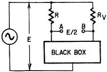
An ac generator is connected to a network consisting of two resistors, R and
RV, and the black box shown in the diagram. It is found that the voltage
between A or B is independent of the value of RV. Whether RV
is shorted or open, the voltage across AB is E/2 where E is the voltage of the generator.
It is also independent of the frequency. Why?
- Qutaiba Bassim El-Dhuwaib
 What Voltage? What Voltage?
Three voltmeters are connected as shown. V1 is an electrostatic type, calibrated
to read peak voltage values. It indicates that the output from the rectifier is
1,000 peak volts. V2 is a dc voltmeter of the d'Arsonval type. V3 is an ac voltmeter
of the electrodynamometer or iron-vane type. What will be the voltage indicated
by voltmeters V2 and V3?
- Kendall Collins
 A Distorted Puzzler A Distorted Puzzler
This could be any voltage amplifier stage - most likely audio. Could also be
a triode. Signal is getting through, but with less than usual volume and with considerable
distortion. The tube is good, the voltages are as shown. The components? Well, better
check 'em. Won't have to disconnect anything to find any bad ones, though. Just
look.
- Jack Darr
Quizzes from vintage electronics magazines such as Popular
Electronics, Electronics-World, QST, Radio-Electronics,
and Radio News were published over the years - some really simple and others
not so simple. Robert P. Balin created most of the quizzes for Popular
Electronics. This is a listing of all I have posted thus far.
- Vacuum Tube Quiz,
February 1961 Popular Electronics
- Kool-Keeping Kwiz, June
1970 Popular Electronics
- Find the Brightest
Bulb Quiz, April 1960 Popular Electronics
-
Where Do the Scientists Belong? - Feb 19, 1949 Saturday Evening Post
- Quiz
on AC Circuit Theory, December 1970 Popular Electronics
- Magnetic
Phenomena Quiz, February 1962 Popular Electronics
- Electronics
Geography Quiz, April 1970 Popular Electronics
- Electronic
Menu Quiz, August 1963 Popular Electronics
- Electronic
Noise Quiz, August 1962 Popular Electronics
- Electronic
Current Quiz, October 1963 Popular Electronics
- Electronic
Inventors Quiz, November 1963 Popular Electronics
- Resistor Function
Quiz, January 1962 Popular Electronics
- Electronic
Measurement Quiz, January 1963 Popular Electronics
- Electronic
Coupling Quiz, August 1973 Popular Electronics
- Electronics
Analogy Quiz, August 1960 Popular Electronics
- Audio Quiz, April
1955 Popular Electronics
- Electronic Unit
Quiz, May 1962 Popular Electronics
- Capacitor
Circuit Quiz, June 1968 Popular Electronics
- Meter-Reading
Quiz, June 1966 Popular Electronics
- Electronic
Geometry Quiz, Jan 1965 Popular Electronics
- Electronic
Factor Quiz, November 1966 Popular Electronics
- Electronics
Math Quiz, November 1965 Popular Electronics
- Series Circuit
Quiz, May 1966 Popular Electronics
- Electrochemistry
Quiz, Mar 1966 Popular Electronics
- Biz
Quiz: Test Your Sales Ability - April 1947 Radio News
- Electronic
Analogy Quiz, Nov 1961 Popular Electronics
- Diode Quiz, July
1961 Popular Electronics
- Electronic
Curves Quiz, Feb 1963 Popular Electronics
- Electronic
Numbers Quiz, Dec 1962 Popular Electronics
- Energy Conversion
Quiz, April 1963 Popular Electronics
- Coil Function
Quiz, June 1962 Popular Electronics
-
Co-Inventors Quiz - January 1965 Electronics World
-
"-Tron" Teasers Quiz - Oct 1963 Electronics World
- Polarity Quiz
- March 1968 Popular Electronics
-
Television
I.Q. Quiz - Oct 1948 Radio & Television News
- Amplifier Quiz
Part I - Feb 1964 Popular Electronics
- Semiconductor
Quiz - Feb 1967 Popular Electronics
- Unknown
Frequency Quiz - September 1965 Popular Electronics
- Electronics
Metals Quiz - Oct 1964 Popular Electronics
- Electronics
Measurement Quiz - August 1967 Popular Electronics
- Vector-Circuit
Matching Quiz, June 1970 Popular Electronics
- Inductance
Quiz, September 1961 Popular Electronics
- RC Circuit Quiz,
June 1963 Popular Electronics
|
-
LCR Circuits Quiz - November 1969 Electronics World
- Amplifier Quiz
Part 2 - March 1964 Popular Electronics
- Amplifier
Quiz Part 1 - February 1964 Popular Electronics
- Three
Letter Quiz - January 1964 Popular Electronics
-
Electromagnetic Function - June 1964 Popular Electronics
-
Electronic Sticklers - February 1959 Popular Electronics
-
Bio-Electronic Quiz - July 1964 Popular Electronics
- Transformer Quiz
- April 1962 Popular Electronics
- Oscilloscope
Quiz - October 1961 Popular Electronics
- Roundword Puzzle
- January 1961 Popular Electronics
- Electronic
Sticklers - April 1959 Popular Electronics
-
What's Your EQ? - August 1966 Radio-Electronics
-
What's Your EQ? - February 1966 Radio-Electronics
-
What's Your EQ? - September 1962 Radio-Electronics
- Electronic Sticklers
- May 1959 Popular Electronics
-
What's Your EQ? - February 1963 Radio-Electronics
-
What's Your EQ? - April 1964 Radio-Electronics
-
What's Your EQ? - October 1966 Radio-Electronics
-
What's Your EQ? - June 1963 Radio-Electronics
-
What's Your EQ? - July 1966 Radio-Electronics
-
What's Your EQ? - December 1966 Radio-Electronics
-
What's Your EQ? - October 1964 Radio-Electronics
-
What's Your EQ? - July 1963 Radio-Electronics
-
What's Your EQ? - March 1966 Radio-Electronics
-
What's Your EQ? - November 1966 Radio-Electronics
-
What's Your EQ? - October 1966 Radio-Electronics
-
What's Your EQ? - May 1966 Radio-Electronics
-
What's Your EQ? - January 1966 Radio-Electronics
-
What's Your EQ - July 1966 Radio-Electronics
-
What's Your EQ? - December 1966 Radio-Electronics
-
What's Your EQ? - October 1964 Radio-Electronics
-
What's Your EQ? - June 1963 Radio-Electronics
-
R-E Puzzler - June 1967 Radio-Electronics
-
What's Your EQ? - January 1963 Radio-Electronics
-
Do You Know the Law? - Nov 1963 Radio-Electronics
-
What's Your EQ? - November 1962 Radio-Electronics
-
What's Your EQ? - September 1966 Radio-Electronics
- Radio
WittiQuiz - October 1938 Radio-Craft
-
What's Your EQ? - November 1964 Radio-Electronics
-
What's Your EQ? - February 1964 Radio-Electronics
-
What's Your EQ? - July 1967 Radio-Electronics
-
What's Your EQ? - December 1962 Radio-Electronics
-
What's Your EQ? - April 1966 Radio-Electronics
-
What's Your EQ? - October 1963 Radio-Electronics
-
What's Your EQ? - July 1964 Radio-Electronics
- Radio
WittiQuiz - November 1937 Radio-Craft
-
What's Your EQ? - May 1967 Radio-Electronics
-
What's Your EQ? - July 1962 Radio-Electronics
-
What's Your EQ? - January 1962 Radio-Electronics
-
What's Your EQ? - February 1962 Radio-Electronics
-
What's Your EQ? - March 1962 Radio-Electronics
-
What's Your EQ? - July 1961 Radio-Electronics
-
What's Your EQ? - August 1961 Radio-Electronics
-
Can You Name These Strange Electronic Effects? - August 1962 Radio-Electronics
-
What's Your EQ? - September 1961 Radio-Electronics
-
What's Your EQ? - September 1962 Radio-Electronics
-
What's Your EQ? - October 1961 Radio-Electronics
- Radio
WittiQuiz - December 1937 Radio-Craft
-
What's Your EQ? - November 1961 Radio-Electronics
-
What's Your EQ? - March 1964 Radio-Electronics
-
What's Your EQ? - April 1962 Radio-Electronics
-
What's Your EQ? - May 1962 Radio-Electronics
-
What's Your EQ? - June 1962 Radio-Electronics
-
What's Your EQ? - April 1967 Radio-Electronics
-
What's Your EQ? - March 1967 Radio-Electronics
-
What's Your EQ? - December 1964 Radio-Electronics
-
What's Your EQ? - January 1967 Radio-Electronics
-
Wanted: 50,000 Engineers - Jan 1953 Popular Mechanics
-
What's Your EQ? - August 1964 Radio-Electronics
- Voltage Quiz
- December 1961 Popular Electronics
-
What is It? - June 1941 Popular Science
- What Do You Know
About Resistors? - April 1974 Popular Electronics
-
What's Your EQ? - September 1963 Radio-Electronics
- Potentiometer Quiz - Sep
1962 Popular Electronics
-
Mathematical Bafflers - March 1965 Mechanix Illustrated
- Op Amp Quiz -
October 1968 Popular Electronics
- Electronic "A"
Quiz - April 1968 Popular Electronics
-
What's Your EQ? - May 1961 Radio-Electronics
-
Popular Science Question Bee - Feb 1939 Popular Science
-
What is It? - A Question Bee in Photographs - June 1941 Popular Science
-
What's Your EQ? - June 1961 Radio-Electronics
-
What's Your EQ? - June 1964 Radio-Electronics
-
What's Your EQ? - May 1964 Radio-Electronics
-
What's Your EQ? - August 1963 Radio-Electronics
-
What's Your EQ? - May 1963 Radio-Electronics
- Bridge
Function Quiz - Sep 1969 Radio-Electronics
-
What's Your EQ? - March 1963 Radio-Electronics
-
What's Your EQ? - February 1967 Radio-Electronics
-
Circuit Quiz - June 1966 Radio-Electronics
-
What's Your EQ? - June 1966 Radio-Electronics
- Electronics
Mathematics Quiz - June 1969 Popular Electronics
- Brightest
Light Quiz - April 1964 Popular Electronics
-
What's Your EQ? - April 1963 Radio-Electronics
- Electronics "B" Quiz
- July 1969 Popular Electronics
- Ohm's Law Quiz
- March 1969 Popular Electronics
-
Antenna Quiz - November 1962 Electronics World
- Color Code Quiz
- November 1967 Popular Electronics
- CapaciQuiz
- August 1961 Popular Electronics
- Transformer
Winding Quiz - Dec 1964 Popular Electronics
-
Audiophile Quiz - November 1957 Radio-electronics
- Capacitor
Function Quiz - Mar 1962 Popular Electronics
- Greek Alphabet
Quiz - December 1963 Popular Electronics
- Circuit
Designer's Name Quiz - July 1968 Popular Electronics
-
Sawtooth Sticklers Quiz - Nov 1960 Radio-Electronics
-
Elementary
Radio Quiz - December 1947 Radio-Craft
- Hi-Fi
Quiz - October 1955 Radio & Television News
- Electronics Physics
Quiz - March 1974 Popular Electronics
- A Baffling Quiz
- January 1968 Popular Electronics
- Electronics IQ
Quiz - May 1967 Popular Electronics
- Plug and Jack
Quiz - Dec 1967 Popular Electronics
- Electronic
Switching Quiz - Oct 1967 Popular Electronics
- Electronic
Angle Quiz - Sep 1967 Popular Electronics
- International
Electronics Quiz - July 1967 Popular Electronics
- FM Radio
Quiz - April 1950 Radio & Television News
- Bridge Circuit
Quiz -Dec 1966 Popular Electronics
- Diode Function
Quiz - August 1965 Popular Electronics
- Diagram Quiz,
August 1966 Popular Electronics
- Quist Quiz - November
1953 QST
- TV Trouble Quiz,
July 1966 Popular Electronics
- Electronics History Quiz,
Dec 1965 Popular Electronics
- Scope-Trace Quiz,
March 1965 Popular Electronics
-
Electronic
Circuit Analogy Quiz, April 1973
-
Test Your Knowledge of Semiconductors, August 1972 Popular Electronics
- Ganged Switching
Quiz, April 1972 Popular Electronics
- Lamp Brightness
Quiz, Jan 1969 Popular Electronics
- Lissajous
Pattern Quiz, Sep 1963 Popular Electronics
- Electronic
Quizoo, October 1962 Popular Electronics
- Electronic
Photo Album Quiz, March 1963 Popular Electronics
- Electronic
Alphabet Quiz, May 1963 Popular Electronics
- Quiz: Resistive?
Inductive? or Capacitive?, October 1960 Popular Electronics
|
These
are the answers. This month's puzzles are on, page 37. If you have an interesting
or unusual puzzle (with an answer) send it to us. We will pay $10 for each one accepted.
We're especially interested in service stinkers or engineering stumpers on actual
electronic equipment. We get so many letters we can't answer individual ones, but
we'll print the more interesting solutions - ones the original authors never thought
of. Write EQ Editor, Radio-Electronics, 154 West 14th Street, New York, N. Y. -
10011.

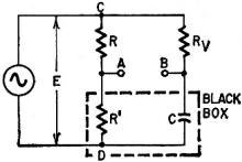
Fig. 1 - Black Box contents.

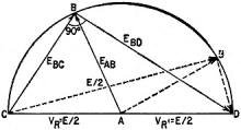
Fig. 2 - Black Box vector voltages
Always Half
The black box contains a capacitor and a resistor equal to R as in Fig. 1. The
voltage ECA = EAD = E/2 having zero angle with E; the voltage
EBC is 90° out of phase with EBD, and the vector sum is equal
to E: consider the modified vector diagram (Fig. 2). EBC is always perpendicular
to EBD, thus point B will fall on the circumference of a circle having
a diameter of E or a radius of E/2. Likewise, as point A falls in the center of
this circle, the distance between A and B will become E/2. Whatever the resistance,
only the phase shift will change.
This circuit is used often as a phase shifter to change phase without changing
amplitude.
Note: This puzzle, in slightly different form, was published as "Output Voltage"
by Cameron McCulloch in the October 1963 issue and evoked a flood of disbelieving
letters as well as criticisms of an attempted abridged mathematical proof (Mr. McCulloch's
proof was much longer than the one printed).
Readers may be assured that the circuit is "bench-tested," that it works, and
is indeed so ruggedly based in theory that an unfortunate change of sign in one
of the terms of the October explanation did not change the final result.
 What Voltage? What Voltage?
The output from the full-wave rectifier consists of negative half-cycles at the
rate of 800 per second. Therefore the output is negative with respect to the center
tap on the transformer secondary.
Unless otherwise stated, dc voltmeter readings should be taken as average values,
and ac voltmeter readings should be taken as rms values. Observing polarity, the
dc voltmeter (V2) reading is 636 volts, determined by multiplying 0.636 times the
peak value of 1,000 volts. The ac voltmeter (V3) reading is 707 volts, determined
by multiplying 0.707 times the peak value of 1,000 volts.
If ac voltmeter V3 is a basic d'Arsonval type, calibrated with and using a half-wave
rectifier, the indicated voltage will be entirely different. This method is used
in some vom instruments. Again observing polarity, the meter would indicate 1,414
volts, or double the rms value, in the forward position and zero volts with the
test leads reversed. The output waveform of the circuit shown in the puzzler, along
with the relative voltages, is shown in the diagram. The 0.636 factor applies to
the average value of a sine wave and also to the output of an unfiltered full-wave
rectifier.
A
Distorted Puzzler
A simple one, and not uncommon. The key is, of course, that 6 volts positive
at the grid, which causes a high plate current and a low plate voltage. Pretty obviously,
the 0.01-μf input coupling capacitor is leaking badly.
From the July 1964 issue:
There is another possible cause of distortion in Jack
Darr's "A Distorted Puzzler," page 37 of the March issue. My solution was that
the 6 volts on the control grid was caused by grid emission. I check for grid
emission by pulling the tube. If the voltage disappears I suspect the tube. If
it remains, I suspect the coupling capacitor. Miniature and subminiature power
tubes are more susceptible to grid emission caused by excessive heat than are
voltage amplifiers - a point Mr. Darr may have had in mind.
- James B. Edgerton
Correction from March 1964
3-Phase Circuit: Out-of-Phase Head! In the matter of getting single-phase voltages
from a 3-phase supply (Power Supply Puzzler, page 39, October 1963): I was wrong!
This was on a conveyor belt, with a photocell-operated shutoff (stopped the motor
when a package got to the end). Everything worked except the photocell unit; it
smoked. By isolating the power transformer, feeding it from single-phase supply,
I could make it work. This started an argument, so I left in the middle of it.
Later, after the argument had begun, I went back and traced it out in more detail.
Fig. 1-a shows how it should have been connected; Fig. 1-b shows how it was connected.
The "contactor coil," part of the motor control, should have been fed from the same
phase that fed the power transformer. Instead, it was connected to another phase,
and to the power transformer at the same time! We got a "vector sum voltage" and
smoke. Things didn't burn up, because there must have been enough inductance in
the circuit to hold the current down. Of course, we could only leave it on for a
few seconds.
Fig. 1 - In correct circuit (a), 240 volts between A and C operates coil
and transformer primary. In no-good circuit (b), there are 2 phases (B-C and B-gnd)
connected into same circuit. Letters refer to terminals in Fig. 2.
Fig. 2 - Actual voltages to be found on 3-phase line.
Fig. 2 shows the true voltages in such a circuit, just as many readers wrote
in to remind me. So, if the members of my Fan Club will lay down those baseball
bats and let me get the egg off my face, I'll apologize! Too fast a diagnosis on
too little evidence.
The Young Electrician said I was wrong. I said he was wrong. In that respect,
at least, we were both right.
- Jack Darr
|


