|
January 1963 Radio-Electronics
 [Table of Contents] [Table of Contents]
Wax nostalgic about and learn from the history of early electronics.
See articles from Radio-Electronics,
published 1930-1988. All copyrights hereby acknowledged.
|
This set of three circuit
analysis challenges appeared in the January 1963 issue of Radio-Electronics
magazine. Readers, staff, and even come companies submitted the "What's Your EQ?"
(EQ = Electronics Quotient) content. As an example of the latter, Cleveland Institute
of Electronics provided "Draw the Waveform." Don't let the diode vacuum tube deter
you from the puzzle. Just mentally replace the tube with a solid state diode symbol
with the anode at the top where the tube's plate (anode) is shown. The negative
element of a tube is called the cathode, same as the solid state diode.
"Capacitor Charge" is easy enough. "Another 2-Box Light" is a form of Black Box
problem. Don't be afraid to think outside the box to figure out what is going on
inside the box!
What's Your EQ?
  Draw the Waveform Draw the Waveform
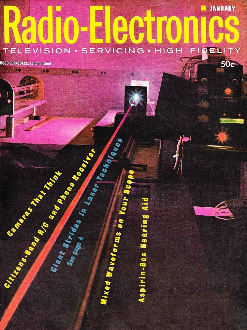
The sine wave with a peak value of 30 volts, shown at the input of circuit, collided
with a diode on its way to the output. As a result, the wave was bent a bit. Draw
in the space provided the shape of the wave at the output. Ignore the voltage drop
across the diode.
- Cleveland Institute of Electronics
 Capacitor Charge Capacitor Charge
Two 1-μf capacitors are connected in series with a 100-volt dc source. A shorting
switch is connected across one of the capacitors. The capacitors are both good.
The shorting switch is pressed, then released. What is the condition of the charge
on the two capacitors immediately after the shorting switch is released?
- V. H. Laughter
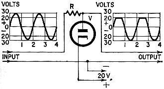
 Another Two-Box Light Another Two-Box Light
Each of the boxes has an spst switch throw and a 120-volt 6-watt indicator lamp
with jewel. The wires are shown in the diagram. The switch in each box operates
the lamp in the opposite box. The boxes are a little larger than is necessary to
enclose the single-pole single-throw switch and the 120-volt lamp and its socket.
What is the circuit? What is in the boxes?
- Almon H. Clegg
Quizzes from vintage electronics magazines (and many custom RF Cafe-generated
quizzes) such as Popular Electronics, Electronics-World,
QST, Radio-Electronics, and Radio News were published
over the years - some really simple and others not so simple. Robert P. Balin
created most of the quizzes for Popular Electronics. This is a listing
of all I have posted thus far.
- Oscillator
Quiz, November 1962 Popular Electronics
- Vacuum Tube Quiz,
February 1961 Popular Electronics
- Kool-Keeping Kwiz, June
1970 Popular Electronics
- Find the Brightest
Bulb Quiz, April 1960 Popular Electronics
-
Where Do the Scientists Belong? - Feb 19, 1949 Saturday Evening Post
- Quiz
on AC Circuit Theory, December 1970 Popular Electronics
- Magnetic
Phenomena Quiz, February 1962 Popular Electronics
- Electronics
Geography Quiz, April 1970 Popular Electronics
- Electronic
Menu Quiz, August 1963 Popular Electronics
- Electronic
Noise Quiz, August 1962 Popular Electronics
- Electronic
Current Quiz, October 1963 Popular Electronics
- Electronic
Inventors Quiz, November 1963 Popular Electronics
- Resistor Function
Quiz, January 1962 Popular Electronics
- Electronic
Measurement Quiz, January 1963 Popular Electronics
- Electronic
Coupling Quiz, August 1973 Popular Electronics
- Electronics
Analogy Quiz, August 1960 Popular Electronics
- Audio Quiz, April
1955 Popular Electronics
- Electronic Unit
Quiz, May 1962 Popular Electronics
- Capacitor
Circuit Quiz, June 1968 Popular Electronics
- Meter-Reading
Quiz, June 1966 Popular Electronics
- Electronic
Geometry Quiz, Jan 1965 Popular Electronics
- Electronic
Factor Quiz, November 1966 Popular Electronics
- Electronics
Math Quiz, November 1965 Popular Electronics
- Series Circuit
Quiz, May 1966 Popular Electronics
- Electrochemistry
Quiz, Mar 1966 Popular Electronics
- Biz
Quiz: Test Your Sales Ability - April 1947 Radio News
- Electronic
Analogy Quiz, Nov 1961 Popular Electronics
- Diode Quiz, July
1961 Popular Electronics
- Electronic
Curves Quiz, Feb 1963 Popular Electronics
- Electronic
Numbers Quiz, Dec 1962 Popular Electronics
- Energy Conversion
Quiz, April 1963 Popular Electronics
- Coil Function
Quiz, June 1962 Popular Electronics
-
Co-Inventors Quiz - January 1965 Electronics World
-
"-Tron" Teasers Quiz - Oct 1963 Electronics World
- Polarity Quiz
- March 1968 Popular Electronics
-
Television
I.Q. Quiz - Oct 1948 Radio & Television News
- Amplifier Quiz
Part I - Feb 1964 Popular Electronics
- Semiconductor
Quiz - Feb 1967 Popular Electronics
- Unknown
Frequency Quiz - September 1965 Popular Electronics
- Electronics
Metals Quiz - Oct 1964 Popular Electronics
- Electronics
Measurement Quiz - August 1967 Popular Electronics
- Vector-Circuit
Matching Quiz, June 1970 Popular Electronics
- Inductance
Quiz, September 1961 Popular Electronics
- RC Circuit Quiz,
June 1963 Popular Electronics
|
-
LCR Circuits Quiz - November 1969 Electronics World
- Amplifier Quiz Part
2 - March 1964 Popular Electronics
- Amplifier Quiz
Part 1 - February 1964 Popular Electronics
- Three Letter
Quiz - January 1964 Popular Electronics
- Electromagnetic
Function - June 1964 Popular Electronics
- Electronic
Sticklers - February 1959 Popular Electronics
- Bio-Electronic
Quiz - July 1964 Popular Electronics
- Transformer Quiz
- April 1962 Popular Electronics
- Oscilloscope
Quiz - October 1961 Popular Electronics
- Roundword Puzzle
- January 1961 Popular Electronics
- Electronic
Sticklers - April 1959 Popular Electronics
-
What's Your EQ? - August 1966 Radio-Electronics
-
What's Your EQ? - February 1966 Radio-Electronics
-
What's Your EQ? - September 1962 Radio-Electronics
- Electronic Sticklers
- May 1959 Popular Electronics
-
What's Your EQ? - February 1963 Radio-Electronics
-
What's Your EQ? - April 1964 Radio-Electronics
-
What's Your EQ? - October 1966 Radio-Electronics
-
What's Your EQ? - June 1963 Radio-Electronics
-
What's Your EQ? - July 1966 Radio-Electronics
-
What's Your EQ? - December 1966 Radio-Electronics
-
What's Your EQ? - October 1964 Radio-Electronics
-
What's Your EQ? - July 1963 Radio-Electronics
-
What's Your EQ? - March 1966 Radio-Electronics
-
What's Your EQ? - November 1966 Radio-Electronics
-
What's Your EQ? - October 1966 Radio-Electronics
-
What's Your EQ? - May 1966 Radio-Electronics
-
What's Your EQ? - January 1966 Radio-Electronics
-
What's Your EQ - July 1966 Radio-Electronics
-
What's Your EQ? - December 1966 Radio-Electronics
-
What's Your EQ? - October 1964 Radio-Electronics
-
What's Your EQ? - June 1963 Radio-Electronics
-
R-E Puzzler - June 1967 Radio-Electronics
-
What's Your EQ? - January 1963 Radio-Electronics
-
Do You Know the Law? - Nov 1963 Radio-Electronics
-
What's Your EQ? - November 1962 Radio-Electronics
-
What's Your EQ? - September 1966 Radio-Electronics
- Radio
WittiQuiz - October 1938 Radio-Craft
-
What's Your EQ? - November 1964 Radio-Electronics
-
What's Your EQ? - February 1964 Radio-Electronics
-
What's Your EQ? - July 1967 Radio-Electronics
-
What's Your EQ? - December 1962 Radio-Electronics
-
What's Your EQ? - April 1966 Radio-Electronics
-
What's Your EQ? - October 1963 Radio-Electronics
-
What's Your EQ? - July 1964 Radio-Electronics
- Radio
WittiQuiz - November 1937 Radio-Craft
-
What's Your EQ? - May 1967 Radio-Electronics
-
What's Your EQ? - July 1962 Radio-Electronics
-
What's Your EQ? - January 1962 Radio-Electronics
-
What's Your EQ? - February 1962 Radio-Electronics
-
What's Your EQ? - March 1962 Radio-Electronics
-
What's Your EQ? - July 1961 Radio-Electronics
-
What's Your EQ? - August 1961 Radio-Electronics
-
Can You Name These Strange Electronic Effects? - August 1962 Radio-Electronics
-
What's Your EQ? - September 1961 Radio-Electronics
-
What's Your EQ? - September 1962 Radio-Electronics
-
What's Your EQ? - October 1961 Radio-Electronics
- Radio
WittiQuiz - December 1937 Radio-Craft
-
What's Your EQ? - November 1961 Radio-Electronics
-
What's Your EQ? - March 1964 Radio-Electronics
-
What's Your EQ? - April 1962 Radio-Electronics
-
What's Your EQ? - May 1962 Radio-Electronics
-
What's Your EQ? - June 1962 Radio-Electronics
-
What's Your EQ? - April 1967 Radio-Electronics
-
What's Your EQ? - March 1967 Radio-Electronics
-
What's Your EQ? - December 1964 Radio-Electronics
-
What's Your EQ? - January 1967 Radio-Electronics
-
Wanted: 50,000 Engineers - Jan 1953 Popular Mechanics
-
What's Your EQ? - August 1964 Radio-Electronics
- Voltage Quiz
- December 1961 Popular Electronics
-
What is It? - June 1941 Popular Science
- What Do You Know
About Resistors? - April 1974 Popular Electronics
-
What's Your EQ? - September 1963 Radio-Electronics
- Potentiometer Quiz - Sep
1962 Popular Electronics
-
Mathematical Bafflers - March 1965 Mechanix Illustrated
- Op Amp Quiz -
October 1968 Popular Electronics
- Electronic "A"
Quiz - April 1968 Popular Electronics
-
What's Your EQ? - May 1961 Radio-Electronics
-
Popular Science Question Bee - Feb 1939 Popular Science
-
What is It? - A Question Bee in Photographs - June 1941 Popular Science
-
What's Your EQ? - June 1961 Radio-Electronics
-
What's Your EQ? - June 1964 Radio-Electronics
-
What's Your EQ? - May 1964 Radio-Electronics
-
What's Your EQ? - August 1963 Radio-Electronics
-
What's Your EQ? - May 1963 Radio-Electronics
- Bridge
Function Quiz - Sep 1969 Radio-Electronics
-
What's Your EQ? - March 1963 Radio-Electronics
-
What's Your EQ? - February 1967 Radio-Electronics
-
Circuit Quiz - June 1966 Radio-Electronics
-
What's Your EQ? - June 1966 Radio-Electronics
- Electronics
Mathematics Quiz - June 1969 Popular Electronics
- Brightest
Light Quiz - April 1964 Popular Electronics
-
What's Your EQ? - April 1963 Radio-Electronics
- Electronics "B" Quiz
- July 1969 Popular Electronics
- Ohm's Law Quiz
- March 1969 Popular Electronics
-
Antenna Quiz - November 1962 Electronics World
- Color Code Quiz
- November 1967 Popular Electronics
- CapaciQuiz
- August 1961 Popular Electronics
- Transformer
Winding Quiz - Dec 1964 Popular Electronics
-
Audiophile Quiz - November 1957 Radio-electronics
- Capacitor
Function Quiz - Mar 1962 Popular Electronics
- Greek Alphabet
Quiz - December 1963 Popular Electronics
- Circuit
Designer's Name Quiz - July 1968 Popular Electronics
-
Sawtooth Sticklers Quiz - Nov 1960 Radio-Electronics
-
Elementary
Radio Quiz - December 1947 Radio-Craft
- Hi-Fi
Quiz - October 1955 Radio & Television News
- Electronics Physics
Quiz - March 1974 Popular Electronics
- A Baffling Quiz
- January 1968 Popular Electronics
- Electronics IQ
Quiz - May 1967 Popular Electronics
- Plug and Jack
Quiz - Dec 1967 Popular Electronics
- Electronic
Switching Quiz - Oct 1967 Popular Electronics
- Electronic
Angle Quiz - Sep 1967 Popular Electronics
- International
Electronics Quiz - July 1967 Popular Electronics
- FM Radio
Quiz - April 1950 Radio & Television News
- Bridge Circuit
Quiz -Dec 1966 Popular Electronics
- Diode Function
Quiz - August 1965 Popular Electronics
- Diagram Quiz,
August 1966 Popular Electronics
- Quist Quiz - November
1953 QST
- TV Trouble Quiz,
July 1966 Popular Electronics
- Electronics History Quiz,
Dec 1965 Popular Electronics
- Scope-Trace Quiz,
March 1965 Popular Electronics
-
Electronic
Circuit Analogy Quiz, April 1973
-
Test Your Knowledge of Semiconductors, August 1972 Popular Electronics
- Ganged Switching
Quiz, April 1972 Popular Electronics
- Lamp Brightness
Quiz, Jan 1969 Popular Electronics
- Lissajous
Pattern Quiz, Sep 1963 Popular Electronics
- Electronic
Quizoo, October 1962 Popular Electronics
- Electronic
Photo Album Quiz, March 1963 Popular Electronics
- Electronic
Alphabet Quiz, May 1963 Popular Electronics
- Quiz: Resistive?
Inductive? or Capacitive?, October 1960 Popular Electronics
|
Answers to What's Your Eq?
These are the answers!
 Draw the Waveform Draw the Waveform
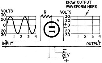
As long as the input signal is less than +20 volts, the diode cannot conduct
and the output signal is the same as the input signal. When the input voltage reaches
20, the tube acts as a short, keeping the voltage from rising any higher.
Capacitor Charge
Since the two capacitors are In series, the 100-volt charge will divide, charging
each to 50 volts. When the shorting switch is pressed, the non-shorted capacitor
(C1) will be charged to 100 volts. When the switch is released, one end of C2 is
connected to the negative side of the battery and the other end to the negatively
charged end of C1. Thus, you will have a 100-volt charge on one capacitor and zero
charge on the other. (This statement does not consider the residual charge left
in the shorted unit.) Due to leakages, the charges will gradually even up, resulting
in a final charge of 50 volts on each capacitor.
 Another Two-Box Problem Another Two-Box Problem
As you have probably guessed, this is also done with rectifiers, and the difference
between it and the earlier problems is in the switching. The diagram below shows
the circuit. The lamps are 120 volts 6 watts, as stated in the problem, and the
rectifiers should be rated at 100 ma or more.
|