|
February 1964 Radio-Electronics
 [Table of Contents] [Table of Contents]
Wax nostalgic about and learn from the history of early electronics.
See articles from Radio-Electronics,
published 1930-1988. All copyrights hereby acknowledged.
|
Put on your thinking
cap again and take a shot at these trio of new circuit analysis problems that
appeared in the "What's Your EQ?" feature in the February 1964 issue of
Radio-Electronics magazine. These days, I'm guessing not too many people
are familiar with the characteristics of neon bulbs, and even way fewer with
vacuum tube circuits. Neon bulbs were one of the earlier forms of voltage
references since once ignited, the voltage drop across them is fairly constant,
sort of like a gaseous Zener diode - except there was zero current flow prior to
ignition. Although I didn't know for sure, I figured that even with its high
input impedance, the VTVM would have an effect on the circuit, or Mr. Collins
wouldn't have bothered to include it. Read on to discover why. "The Innocent Black Box"
ended up having a different solution than my assumption. Oh well. "A No-Signal
Stinker" has a low-tech solution, which I also didn't think of. My suggestion was
that some joker turned the 2.5 MΩ bias potentiometer down.
What's Your EQ?
 Three puzzlers for the student, theoretician
and practical man. Simple? Double-check your answers before you say you've solved
them. If you have an interesting or unusual puzzle (with an answer) send it to us.
We will pay $10 for each one accepted. We're especially interested in service stinkers
or engineering stumpers on actual electronic equipment. We get so many letters we
can't answer individual ones, but we'll print the more interesting solutions - ones
the original authors never thought of. Three puzzlers for the student, theoretician
and practical man. Simple? Double-check your answers before you say you've solved
them. If you have an interesting or unusual puzzle (with an answer) send it to us.
We will pay $10 for each one accepted. We're especially interested in service stinkers
or engineering stumpers on actual electronic equipment. We get so many letters we
can't answer individual ones, but we'll print the more interesting solutions - ones
the original authors never thought of.
Write EQ Editor, Radio-Electronics, 154 West 14th Street, New York, N. Y. - 10011.
Answers to this month's puzzles are on page 62.
 Neon-Bulb Circuit Neon-Bulb Circuit
In the circuit shown, one neon lamp requires a minimum of 74 volts for ionization
and four in series require a minimum of 296. After ionization, the drop across each
lamp is 59 volts and the total current 0.3 ma.
Assuming that the lamps are non-conducting when switch S is closed (because 266
volts is not enough to start conduction), what change will occur when a vtvm with
an input resistance of 10 megohms is connected across terminals A and B? Also, what
reading will the voltmeter have and what will happen when the voltmeter is disconnected
from the circuit?
- Kendall Collins
The Innocent Black Box
A black box has only two terminals. When I use an ohmmeter to check the resistance
in the R x 1 range, the meter reads 25 ohms. When I change the range to R x 10, the meter reads only 10 ohms. The meter has been recently
checked for calibration and is good. The black box does not contain any voltage
source. What does it contain?
- H. D. Varadarajan
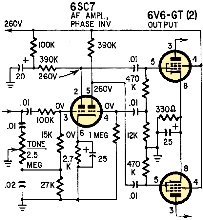
A No-Signal Stinker
In this old Stromberg-Carlson radio (1210), there is no signal through the 6SC7
stage. The tube is new and good. B-plus voltages are OK, all resistors and capacitors
are good, and measure close to rated values. What's wrong?
- Jack Darr
Quizzes from vintage electronics magazines (and many custom RF Cafe-generated
quizzes) such as Popular Electronics, Electronics-World,
QST, Radio-Electronics, and Radio News were published
over the years - some really simple and others not so simple. Robert P. Balin
created most of the quizzes for Popular Electronics. This is a listing
of all I have posted thus far.
- Oscillator
Quiz, November 1962 Popular Electronics
- Vacuum Tube Quiz,
February 1961 Popular Electronics
- Kool-Keeping Kwiz, June
1970 Popular Electronics
- Find the Brightest
Bulb Quiz, April 1960 Popular Electronics
-
Where Do the Scientists Belong? - Feb 19, 1949 Saturday Evening Post
- Quiz
on AC Circuit Theory, December 1970 Popular Electronics
- Magnetic
Phenomena Quiz, February 1962 Popular Electronics
- Electronics
Geography Quiz, April 1970 Popular Electronics
- Electronic
Menu Quiz, August 1963 Popular Electronics
- Electronic
Noise Quiz, August 1962 Popular Electronics
- Electronic
Current Quiz, October 1963 Popular Electronics
- Electronic
Inventors Quiz, November 1963 Popular Electronics
- Resistor Function
Quiz, January 1962 Popular Electronics
- Electronic
Measurement Quiz, January 1963 Popular Electronics
- Electronic
Coupling Quiz, August 1973 Popular Electronics
- Electronics
Analogy Quiz, August 1960 Popular Electronics
- Audio Quiz, April
1955 Popular Electronics
- Electronic Unit
Quiz, May 1962 Popular Electronics
- Capacitor
Circuit Quiz, June 1968 Popular Electronics
- Meter-Reading
Quiz, June 1966 Popular Electronics
- Electronic
Geometry Quiz, Jan 1965 Popular Electronics
- Electronic
Factor Quiz, November 1966 Popular Electronics
- Electronics
Math Quiz, November 1965 Popular Electronics
- Series Circuit
Quiz, May 1966 Popular Electronics
- Electrochemistry
Quiz, Mar 1966 Popular Electronics
- Biz
Quiz: Test Your Sales Ability - April 1947 Radio News
- Electronic
Analogy Quiz, Nov 1961 Popular Electronics
- Diode Quiz, July
1961 Popular Electronics
- Electronic
Curves Quiz, Feb 1963 Popular Electronics
- Electronic
Numbers Quiz, Dec 1962 Popular Electronics
- Energy Conversion
Quiz, April 1963 Popular Electronics
- Coil Function
Quiz, June 1962 Popular Electronics
-
Co-Inventors Quiz - January 1965 Electronics World
-
"-Tron" Teasers Quiz - Oct 1963 Electronics World
- Polarity Quiz
- March 1968 Popular Electronics
-
Television
I.Q. Quiz - Oct 1948 Radio & Television News
- Amplifier Quiz
Part I - Feb 1964 Popular Electronics
- Semiconductor
Quiz - Feb 1967 Popular Electronics
- Unknown
Frequency Quiz - September 1965 Popular Electronics
- Electronics
Metals Quiz - Oct 1964 Popular Electronics
- Electronics
Measurement Quiz - August 1967 Popular Electronics
- Vector-Circuit
Matching Quiz, June 1970 Popular Electronics
- Inductance
Quiz, September 1961 Popular Electronics
- RC Circuit Quiz,
June 1963 Popular Electronics
|
-
LCR Circuits Quiz - November 1969 Electronics World
- Amplifier Quiz Part
2 - March 1964 Popular Electronics
- Amplifier Quiz
Part 1 - February 1964 Popular Electronics
- Three Letter
Quiz - January 1964 Popular Electronics
- Electromagnetic
Function - June 1964 Popular Electronics
- Electronic
Sticklers - February 1959 Popular Electronics
- Bio-Electronic
Quiz - July 1964 Popular Electronics
- Transformer Quiz
- April 1962 Popular Electronics
- Oscilloscope
Quiz - October 1961 Popular Electronics
- Roundword Puzzle
- January 1961 Popular Electronics
- Electronic
Sticklers - April 1959 Popular Electronics
-
What's Your EQ? - August 1966 Radio-Electronics
-
What's Your EQ? - February 1966 Radio-Electronics
-
What's Your EQ? - September 1962 Radio-Electronics
- Electronic Sticklers
- May 1959 Popular Electronics
-
What's Your EQ? - February 1963 Radio-Electronics
-
What's Your EQ? - April 1964 Radio-Electronics
-
What's Your EQ? - October 1966 Radio-Electronics
-
What's Your EQ? - June 1963 Radio-Electronics
-
What's Your EQ? - July 1966 Radio-Electronics
-
What's Your EQ? - December 1966 Radio-Electronics
-
What's Your EQ? - October 1964 Radio-Electronics
-
What's Your EQ? - July 1963 Radio-Electronics
-
What's Your EQ? - March 1966 Radio-Electronics
-
What's Your EQ? - November 1966 Radio-Electronics
-
What's Your EQ? - October 1966 Radio-Electronics
-
What's Your EQ? - May 1966 Radio-Electronics
-
What's Your EQ? - January 1966 Radio-Electronics
-
What's Your EQ - July 1966 Radio-Electronics
-
What's Your EQ? - December 1966 Radio-Electronics
-
What's Your EQ? - October 1964 Radio-Electronics
-
What's Your EQ? - June 1963 Radio-Electronics
-
R-E Puzzler - June 1967 Radio-Electronics
-
What's Your EQ? - January 1963 Radio-Electronics
-
Do You Know the Law? - Nov 1963 Radio-Electronics
-
What's Your EQ? - November 1962 Radio-Electronics
-
What's Your EQ? - September 1966 Radio-Electronics
- Radio
WittiQuiz - October 1938 Radio-Craft
-
What's Your EQ? - November 1964 Radio-Electronics
-
What's Your EQ? - February 1964 Radio-Electronics
-
What's Your EQ? - July 1967 Radio-Electronics
-
What's Your EQ? - December 1962 Radio-Electronics
-
What's Your EQ? - April 1966 Radio-Electronics
-
What's Your EQ? - October 1963 Radio-Electronics
-
What's Your EQ? - July 1964 Radio-Electronics
- Radio
WittiQuiz - November 1937 Radio-Craft
-
What's Your EQ? - May 1967 Radio-Electronics
-
What's Your EQ? - July 1962 Radio-Electronics
-
What's Your EQ? - January 1962 Radio-Electronics
-
What's Your EQ? - February 1962 Radio-Electronics
-
What's Your EQ? - March 1962 Radio-Electronics
-
What's Your EQ? - July 1961 Radio-Electronics
-
What's Your EQ? - August 1961 Radio-Electronics
-
Can You Name These Strange Electronic Effects? - August 1962 Radio-Electronics
-
What's Your EQ? - September 1961 Radio-Electronics
-
What's Your EQ? - September 1962 Radio-Electronics
-
What's Your EQ? - October 1961 Radio-Electronics
- Radio
WittiQuiz - December 1937 Radio-Craft
-
What's Your EQ? - November 1961 Radio-Electronics
-
What's Your EQ? - March 1964 Radio-Electronics
-
What's Your EQ? - April 1962 Radio-Electronics
-
What's Your EQ? - May 1962 Radio-Electronics
-
What's Your EQ? - June 1962 Radio-Electronics
-
What's Your EQ? - April 1967 Radio-Electronics
-
What's Your EQ? - March 1967 Radio-Electronics
-
What's Your EQ? - December 1964 Radio-Electronics
-
What's Your EQ? - January 1967 Radio-Electronics
-
Wanted: 50,000 Engineers - Jan 1953 Popular Mechanics
-
What's Your EQ? - August 1964 Radio-Electronics
- Voltage Quiz
- December 1961 Popular Electronics
-
What is It? - June 1941 Popular Science
- What Do You Know
About Resistors? - April 1974 Popular Electronics
-
What's Your EQ? - September 1963 Radio-Electronics
- Potentiometer Quiz - Sep
1962 Popular Electronics
-
Mathematical Bafflers - March 1965 Mechanix Illustrated
- Op Amp Quiz -
October 1968 Popular Electronics
- Electronic "A"
Quiz - April 1968 Popular Electronics
-
What's Your EQ? - May 1961 Radio-Electronics
-
Popular Science Question Bee - Feb 1939 Popular Science
-
What is It? - A Question Bee in Photographs - June 1941 Popular Science
-
What's Your EQ? - June 1961 Radio-Electronics
-
What's Your EQ? - June 1964 Radio-Electronics
-
What's Your EQ? - May 1964 Radio-Electronics
-
What's Your EQ? - August 1963 Radio-Electronics
-
What's Your EQ? - May 1963 Radio-Electronics
- Bridge
Function Quiz - Sep 1969 Radio-Electronics
-
What's Your EQ? - March 1963 Radio-Electronics
-
What's Your EQ? - February 1967 Radio-Electronics
-
Circuit Quiz - June 1966 Radio-Electronics
-
What's Your EQ? - June 1966 Radio-Electronics
- Electronics
Mathematics Quiz - June 1969 Popular Electronics
- Brightest
Light Quiz - April 1964 Popular Electronics
-
What's Your EQ? - April 1963 Radio-Electronics
- Electronics "B" Quiz
- July 1969 Popular Electronics
- Ohm's Law Quiz
- March 1969 Popular Electronics
-
Antenna Quiz - November 1962 Electronics World
- Color Code Quiz
- November 1967 Popular Electronics
- CapaciQuiz
- August 1961 Popular Electronics
- Transformer
Winding Quiz - Dec 1964 Popular Electronics
-
Audiophile Quiz - November 1957 Radio-electronics
- Capacitor
Function Quiz - Mar 1962 Popular Electronics
- Greek Alphabet
Quiz - December 1963 Popular Electronics
- Circuit
Designer's Name Quiz - July 1968 Popular Electronics
-
Sawtooth Sticklers Quiz - Nov 1960 Radio-Electronics
-
Elementary
Radio Quiz - December 1947 Radio-Craft
- Hi-Fi
Quiz - October 1955 Radio & Television News
- Electronics Physics
Quiz - March 1974 Popular Electronics
- A Baffling Quiz
- January 1968 Popular Electronics
- Electronics IQ
Quiz - May 1967 Popular Electronics
- Plug and Jack
Quiz - Dec 1967 Popular Electronics
- Electronic
Switching Quiz - Oct 1967 Popular Electronics
- Electronic
Angle Quiz - Sep 1967 Popular Electronics
- International
Electronics Quiz - July 1967 Popular Electronics
- FM Radio
Quiz - April 1950 Radio & Television News
- Bridge Circuit
Quiz -Dec 1966 Popular Electronics
- Diode Function
Quiz - August 1965 Popular Electronics
- Diagram Quiz,
August 1966 Popular Electronics
- Quist Quiz - November
1953 QST
- TV Trouble Quiz,
July 1966 Popular Electronics
- Electronics History Quiz,
Dec 1965 Popular Electronics
- Scope-Trace Quiz,
March 1965 Popular Electronics
-
Electronic
Circuit Analogy Quiz, April 1973
-
Test Your Knowledge of Semiconductors, August 1972 Popular Electronics
- Ganged Switching
Quiz, April 1972 Popular Electronics
- Lamp Brightness
Quiz, Jan 1969 Popular Electronics
- Lissajous
Pattern Quiz, Sep 1963 Popular Electronics
- Electronic
Quizoo, October 1962 Popular Electronics
- Electronic
Photo Album Quiz, March 1963 Popular Electronics
- Electronic
Alphabet Quiz, May 1963 Popular Electronics
- Quiz: Resistive?
Inductive? or Capacitive?, October 1960 Popular Electronics
|
Answers to What's Your Eq?
This month's puzzles are on page 57
Neon-bulb circuit
The purpose of the voltmeter is to start the four neon lamps on a voltage lower
than the combined firing voltage of four lamps. For several microseconds after the
vtvm is connected across terminals A and B, the IR drop across both the ballast
resistor and the voltmeter is low, and as a result, most of the supply voltage is
applied to three lamps. This voltage level is above the combined firing voltage
of three lamps and the lamps fire.
When the three unbridged lamps are lit, the rise in current produces an IR drop
that exceeds 74 volts across the 10- megohm voltmeter resistance. This causes the
bridged lamp to fire. After four lamps have fired, the maintaining voltage across
each lamp is 59, and the IR drop across the ballast resistor is 30 volts. For practical
purposes, the voltmeter reading is 59 volts. When the voltmeter is disconnected,
the lamps will continue to glow and the total current will decrease by approximately
6 micro-amperes.
The Innocent Black Box
The black box contains a flashlight bulb. An ohmmeter allows a high circuit current
of 50 to 80 ma (normally) for reading low ohms in the R x 1 range. This heats the
lamp filament and the meter reads hot resistance. But in the R x 10 range, current
is very low and meter reads almost cold resistance.
No-signal stinker
Only one possibility here. (Note that there is no voltage drop across those big
plate resistors!) Grid voltage is zero, cathode voltage zero, so the tube isn't
blocked. The tube heater is not burning! Since the tube is good, this is probably
a socket trouble. This is a metal tube, so you wouldn't see it at first; you'd have
to wait for it to get warm. Check: measure heater voltage on the ends of the base
pins, not on the socket terminals.
|


