|
April 1959 Popular Electronics
 Table
of Contents Table
of Contents
Wax nostalgic about and learn from the history of early electronics. See articles
from
Popular Electronics,
published October 1954 - April 1985. All copyrights are hereby acknowledged.
|
Here is another of the Electronic
Sticklers challenges from Popular Electronics magazine (see May
Electronic
Sticklers). These are fairly basic circuit analysis problems that often can
be solved by inspection, but sometimes a pencil and paper are necessary. Re-drawing
the circuit in a different configuration to make the connections more obvious often
helps when solving total resistance, capacitance, inductance, etc., as in question
#1. In this case, though, you need to be able to recognize a common configuration
to be able to simplify the circuit; otherwise, you'll be writing and solving mesh
equations. #2 has a simple answer and a more elaborate possibility. #3 and #4 are
simple inspection problems. See also
February,
April, and May
Electronic Sticklers.
Electronic Sticklers
These four thought-twisters are arranged in order of increasing difficulty.
 1) Harvey Matrix discovered this network covered
with solder, in his junk box (above). Rather than trust his ancient ohmmeter, he
tried unsuccessfully to compute the resistance mathematically. Show Harvey you are
slicker and quicker by solving the problem in one minute. 1) Harvey Matrix discovered this network covered
with solder, in his junk box (above). Rather than trust his ancient ohmmeter, he
tried unsuccessfully to compute the resistance mathematically. Show Harvey you are
slicker and quicker by solving the problem in one minute.
--Dennis Wroblewski

2) Joe Whatsit had a black box with only two terminals showing (above). To find
out what was in the box, Joe connected a 1 1/2-volt dry cell to the two terminals
and noted the current flow. He then connected a second identical dry cell in series
with the first cell and repeated the experiment. The same current was noted. With
this information, Joe figured out what was in the box. Can you?
--David Borenstein

3) Mr. Pennypincher, in order to save money on batteries for his portable radio,
built this little voltage supply (to the right) to substitute for the batteries.
When he plugged in the unit, he was running a risk of a blown-out component. Any
idea why?
--Ronald Wilensky
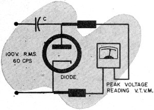
4) With the setup shown (to the left), a diode in series with a capacitor, Harold
Tinkertoy applied 100 volts r.m.s. across the circuit. Then he used his vacuum-tube
voltmeter to measure the peak voltage across the diode. How much did he measure?
To make the problem easy, assume that a sine wave is applied to the circuit.
--Louis E. Garner, Jr.
Quizzes from vintage electronics magazines (and many custom RF Cafe-generated
quizzes) such as Popular Electronics, Electronics-World,
QST, Radio-Electronics, and Radio News were published
over the years - some really simple and others not so simple. Robert P. Balin
created most of the quizzes for Popular Electronics. This is a listing
of all I have posted thus far.
- Oscillator
Quiz, November 1962 Popular Electronics
- Vacuum Tube Quiz,
February 1961 Popular Electronics
- Kool-Keeping Kwiz, June
1970 Popular Electronics
- Find the Brightest
Bulb Quiz, April 1960 Popular Electronics
-
Where Do the Scientists Belong? - Feb 19, 1949 Saturday Evening Post
- Quiz
on AC Circuit Theory, December 1970 Popular Electronics
- Magnetic
Phenomena Quiz, February 1962 Popular Electronics
- Electronics
Geography Quiz, April 1970 Popular Electronics
- Electronic
Menu Quiz, August 1963 Popular Electronics
- Electronic
Noise Quiz, August 1962 Popular Electronics
- Electronic
Current Quiz, October 1963 Popular Electronics
- Electronic
Inventors Quiz, November 1963 Popular Electronics
- Resistor Function
Quiz, January 1962 Popular Electronics
- Electronic
Measurement Quiz, January 1963 Popular Electronics
- Electronic
Coupling Quiz, August 1973 Popular Electronics
- Electronics
Analogy Quiz, August 1960 Popular Electronics
- Audio Quiz, April
1955 Popular Electronics
- Electronic Unit
Quiz, May 1962 Popular Electronics
- Capacitor
Circuit Quiz, June 1968 Popular Electronics
- Meter-Reading
Quiz, June 1966 Popular Electronics
- Electronic
Geometry Quiz, Jan 1965 Popular Electronics
- Electronic
Factor Quiz, November 1966 Popular Electronics
- Electronics
Math Quiz, November 1965 Popular Electronics
- Series Circuit
Quiz, May 1966 Popular Electronics
- Electrochemistry
Quiz, Mar 1966 Popular Electronics
- Biz
Quiz: Test Your Sales Ability - April 1947 Radio News
- Electronic
Analogy Quiz, Nov 1961 Popular Electronics
- Diode Quiz, July
1961 Popular Electronics
- Electronic
Curves Quiz, Feb 1963 Popular Electronics
- Electronic
Numbers Quiz, Dec 1962 Popular Electronics
- Energy Conversion
Quiz, April 1963 Popular Electronics
- Coil Function
Quiz, June 1962 Popular Electronics
-
Co-Inventors Quiz - January 1965 Electronics World
-
"-Tron" Teasers Quiz - Oct 1963 Electronics World
- Polarity Quiz
- March 1968 Popular Electronics
-
Television
I.Q. Quiz - Oct 1948 Radio & Television News
- Amplifier Quiz
Part I - Feb 1964 Popular Electronics
- Semiconductor
Quiz - Feb 1967 Popular Electronics
- Unknown
Frequency Quiz - September 1965 Popular Electronics
- Electronics
Metals Quiz - Oct 1964 Popular Electronics
- Electronics
Measurement Quiz - August 1967 Popular Electronics
- Vector-Circuit
Matching Quiz, June 1970 Popular Electronics
- Inductance
Quiz, September 1961 Popular Electronics
- RC Circuit Quiz,
June 1963 Popular Electronics
|
-
LCR Circuits Quiz - November 1969 Electronics World
- Amplifier Quiz Part
2 - March 1964 Popular Electronics
- Amplifier Quiz
Part 1 - February 1964 Popular Electronics
- Three Letter
Quiz - January 1964 Popular Electronics
- Electromagnetic
Function - June 1964 Popular Electronics
- Electronic
Sticklers - February 1959 Popular Electronics
- Bio-Electronic
Quiz - July 1964 Popular Electronics
- Transformer Quiz
- April 1962 Popular Electronics
- Oscilloscope
Quiz - October 1961 Popular Electronics
- Roundword Puzzle
- January 1961 Popular Electronics
- Electronic
Sticklers - April 1959 Popular Electronics
-
What's Your EQ? - August 1966 Radio-Electronics
-
What's Your EQ? - February 1966 Radio-Electronics
-
What's Your EQ? - September 1962 Radio-Electronics
- Electronic Sticklers
- May 1959 Popular Electronics
-
What's Your EQ? - February 1963 Radio-Electronics
-
What's Your EQ? - April 1964 Radio-Electronics
-
What's Your EQ? - October 1966 Radio-Electronics
-
What's Your EQ? - June 1963 Radio-Electronics
-
What's Your EQ? - July 1966 Radio-Electronics
-
What's Your EQ? - December 1966 Radio-Electronics
-
What's Your EQ? - October 1964 Radio-Electronics
-
What's Your EQ? - July 1963 Radio-Electronics
-
What's Your EQ? - March 1966 Radio-Electronics
-
What's Your EQ? - November 1966 Radio-Electronics
-
What's Your EQ? - October 1966 Radio-Electronics
-
What's Your EQ? - May 1966 Radio-Electronics
-
What's Your EQ? - January 1966 Radio-Electronics
-
What's Your EQ - July 1966 Radio-Electronics
-
What's Your EQ? - December 1966 Radio-Electronics
-
What's Your EQ? - October 1964 Radio-Electronics
-
What's Your EQ? - June 1963 Radio-Electronics
-
R-E Puzzler - June 1967 Radio-Electronics
-
What's Your EQ? - January 1963 Radio-Electronics
-
Do You Know the Law? - Nov 1963 Radio-Electronics
-
What's Your EQ? - November 1962 Radio-Electronics
-
What's Your EQ? - September 1966 Radio-Electronics
- Radio
WittiQuiz - October 1938 Radio-Craft
-
What's Your EQ? - November 1964 Radio-Electronics
-
What's Your EQ? - February 1964 Radio-Electronics
-
What's Your EQ? - July 1967 Radio-Electronics
-
What's Your EQ? - December 1962 Radio-Electronics
-
What's Your EQ? - April 1966 Radio-Electronics
-
What's Your EQ? - October 1963 Radio-Electronics
-
What's Your EQ? - July 1964 Radio-Electronics
- Radio
WittiQuiz - November 1937 Radio-Craft
-
What's Your EQ? - May 1967 Radio-Electronics
-
What's Your EQ? - July 1962 Radio-Electronics
-
What's Your EQ? - January 1962 Radio-Electronics
-
What's Your EQ? - February 1962 Radio-Electronics
-
What's Your EQ? - March 1962 Radio-Electronics
-
What's Your EQ? - July 1961 Radio-Electronics
-
What's Your EQ? - August 1961 Radio-Electronics
-
Can You Name These Strange Electronic Effects? - August 1962 Radio-Electronics
-
What's Your EQ? - September 1961 Radio-Electronics
-
What's Your EQ? - September 1962 Radio-Electronics
-
What's Your EQ? - October 1961 Radio-Electronics
- Radio
WittiQuiz - December 1937 Radio-Craft
-
What's Your EQ? - November 1961 Radio-Electronics
-
What's Your EQ? - March 1964 Radio-Electronics
-
What's Your EQ? - April 1962 Radio-Electronics
-
What's Your EQ? - May 1962 Radio-Electronics
-
What's Your EQ? - June 1962 Radio-Electronics
-
What's Your EQ? - April 1967 Radio-Electronics
-
What's Your EQ? - March 1967 Radio-Electronics
-
What's Your EQ? - December 1964 Radio-Electronics
-
What's Your EQ? - January 1967 Radio-Electronics
-
Wanted: 50,000 Engineers - Jan 1953 Popular Mechanics
-
What's Your EQ? - August 1964 Radio-Electronics
- Voltage Quiz
- December 1961 Popular Electronics
-
What is It? - June 1941 Popular Science
- What Do You Know
About Resistors? - April 1974 Popular Electronics
-
What's Your EQ? - September 1963 Radio-Electronics
- Potentiometer Quiz - Sep
1962 Popular Electronics
-
Mathematical Bafflers - March 1965 Mechanix Illustrated
- Op Amp Quiz -
October 1968 Popular Electronics
- Electronic "A"
Quiz - April 1968 Popular Electronics
-
What's Your EQ? - May 1961 Radio-Electronics
-
Popular Science Question Bee - Feb 1939 Popular Science
-
What is It? - A Question Bee in Photographs - June 1941 Popular Science
-
What's Your EQ? - June 1961 Radio-Electronics
-
What's Your EQ? - June 1964 Radio-Electronics
-
What's Your EQ? - May 1964 Radio-Electronics
-
What's Your EQ? - August 1963 Radio-Electronics
-
What's Your EQ? - May 1963 Radio-Electronics
- Bridge
Function Quiz - Sep 1969 Radio-Electronics
-
What's Your EQ? - March 1963 Radio-Electronics
-
What's Your EQ? - February 1967 Radio-Electronics
-
Circuit Quiz - June 1966 Radio-Electronics
-
What's Your EQ? - June 1966 Radio-Electronics
- Electronics
Mathematics Quiz - June 1969 Popular Electronics
- Brightest
Light Quiz - April 1964 Popular Electronics
-
What's Your EQ? - April 1963 Radio-Electronics
- Electronics "B" Quiz
- July 1969 Popular Electronics
- Ohm's Law Quiz
- March 1969 Popular Electronics
-
Antenna Quiz - November 1962 Electronics World
- Color Code Quiz
- November 1967 Popular Electronics
- CapaciQuiz
- August 1961 Popular Electronics
- Transformer
Winding Quiz - Dec 1964 Popular Electronics
-
Audiophile Quiz - November 1957 Radio-electronics
- Capacitor
Function Quiz - Mar 1962 Popular Electronics
- Greek Alphabet
Quiz - December 1963 Popular Electronics
- Circuit
Designer's Name Quiz - July 1968 Popular Electronics
-
Sawtooth Sticklers Quiz - Nov 1960 Radio-Electronics
-
Elementary
Radio Quiz - December 1947 Radio-Craft
- Hi-Fi
Quiz - October 1955 Radio & Television News
- Electronics Physics
Quiz - March 1974 Popular Electronics
- A Baffling Quiz
- January 1968 Popular Electronics
- Electronics IQ
Quiz - May 1967 Popular Electronics
- Plug and Jack
Quiz - Dec 1967 Popular Electronics
- Electronic
Switching Quiz - Oct 1967 Popular Electronics
- Electronic
Angle Quiz - Sep 1967 Popular Electronics
- International
Electronics Quiz - July 1967 Popular Electronics
- FM Radio
Quiz - April 1950 Radio & Television News
- Bridge Circuit
Quiz -Dec 1966 Popular Electronics
- Diode Function
Quiz - August 1965 Popular Electronics
- Diagram Quiz,
August 1966 Popular Electronics
- Quist Quiz - November
1953 QST
- TV Trouble Quiz,
July 1966 Popular Electronics
- Electronics History Quiz,
Dec 1965 Popular Electronics
- Scope-Trace Quiz,
March 1965 Popular Electronics
-
Electronic
Circuit Analogy Quiz, April 1973
-
Test Your Knowledge of Semiconductors, August 1972 Popular Electronics
- Ganged Switching
Quiz, April 1972 Popular Electronics
- Lamp Brightness
Quiz, Jan 1969 Popular Electronics
- Lissajous
Pattern Quiz, Sep 1963 Popular Electronics
- Electronic
Quizoo, October 1962 Popular Electronics
- Electronic
Photo Album Quiz, March 1963 Popular Electronics
- Electronic
Alphabet Quiz, May 1963 Popular Electronics
- Quiz: Resistive?
Inductive? or Capacitive?, October 1960 Popular Electronics
|
Answers to Electronic: Sticklers
1. Two ohms. Redraw the network schematic in the form of a bridge circuit. You
will find that the resistance values of the bridge legs result in a balanced bridge.
Hence the 3-ohm resistor is an inactive component and can be omitted from the circuit.
All that remains are two series resistance circuits in parallel.
2. A short circuit. The current remains the same since the two dry cells provide
not only twice the voltage but also twice the internal resistance. (Kirt note: It
could also contain a constant current circuit)
3. Since there is no surge resistor, the charging current of the capacitor would
pull too much current through the rectifier. Without the surge resistor (20 cents),
there's a good chance the rectifier ($1.00) would burn out.
4. About 282 volts! How come? On one half-cycle, when the diode's plate is positive,
the capacitor charges to peak line voltage... or about 141 volts (1.41 multiplied
by line voltage). On the next half cycle, the capacitor's voltage is in series with
the peak line voltage and thus adds to it... and 141 plus 141 equals 282! This arrangement,
incidentally, is basic to voltage-doubler power supply design.
If you know of a tricky Electronic Stickler, send it with the solution to the
editors of POPULAR ELECTRONICS. If it is accepted, we will send you a $5 check.
Write each Stickler you would like to submit on the back of a postcard. Submit as
many postcards as you like but, please, just one Stickler per postcard. Send to:
POPULAR ELECTRONICS STICKLERS, One Park Ave., New York 16, N. Y. Sorry, but we will
not be able to return unused Sticklers.
|